2D Calibration: Why XY Motion Accuracy Requires More Than Individual Axis Specifications
How automated 2D error mapping improves positioning accuracy, compensates for cross-axis errors, and helps precision motion systems achieve tighter manufacturing tolerances
Why Individual Axis Accuracy Does Not Tell the Whole Story
A precision linear stage may deliver excellent positioning accuracy when measured independently. However, once two stages are combined into an XY system, mounted on a machine frame, and operated under application-specific conditions, the resulting positioning accuracy can differ considerably from what the individual stage specifications suggest.

The reason is straightforward: a two-axis motion system is more than the sum of its individual axes.
Mechanical alignment, orthogonality errors, angular deviations, mounting conditions, payload, and interactions between the axes all influence the actual position of the working point. Traditional single-axis calibration cannot fully account for these effects.

In a technical webinar, PI engineers demonstrated how automated 2D calibration addresses these limitations. In one measurement example, the two-dimensional positioning error was reduced by a factor of 20.
The Limitations of Conventional 1D Calibration
Single-axis linear stage calibration is a well-established method for improving positioning accuracy.
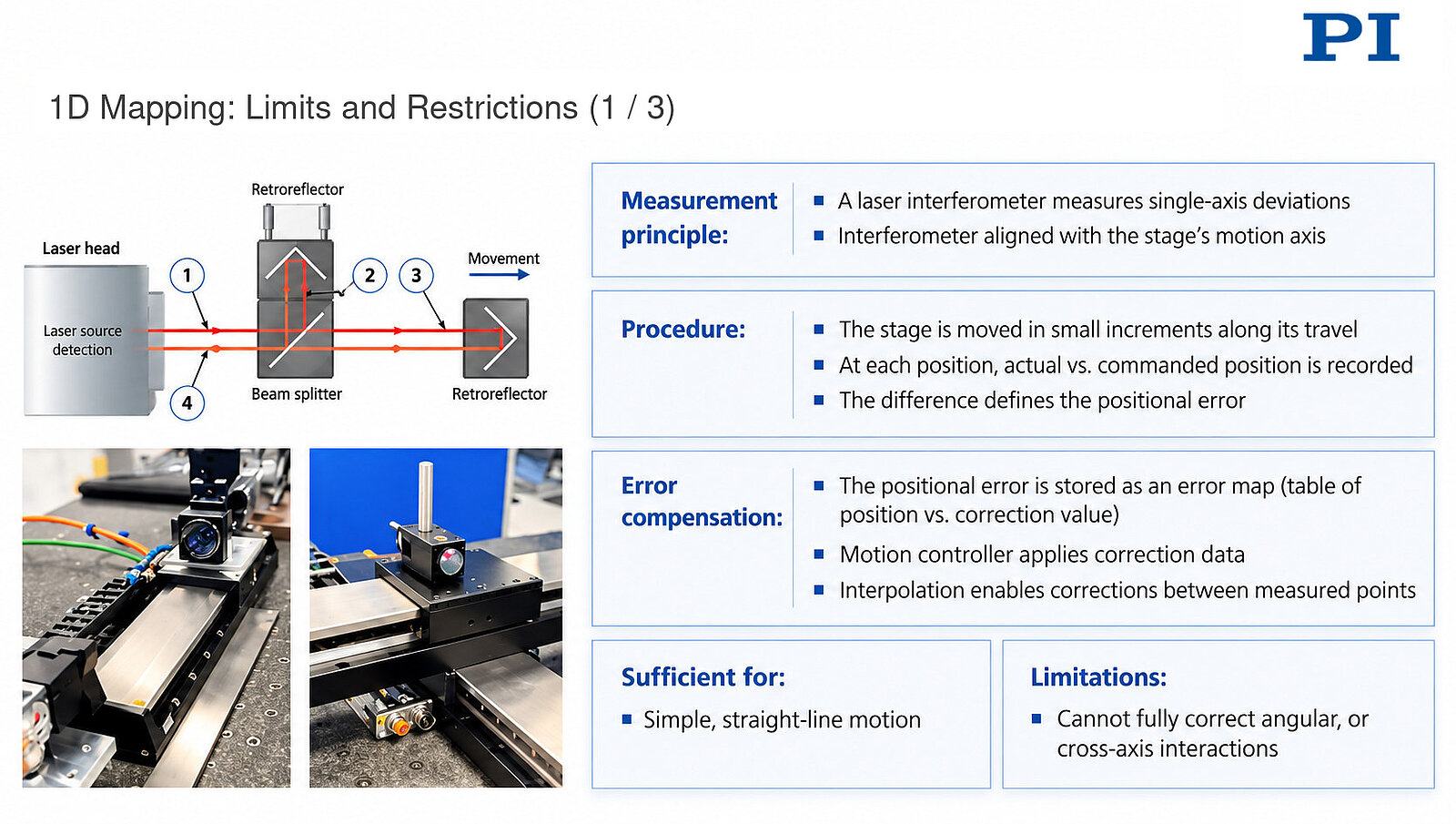
Typically, a laser interferometer measures the difference between the commanded and actual positions along a stage’s travel. The deviations are recorded in a correction table and stored in the motion controller. Because it is not practical to measure every possible position, the controller interpolates between the measured points when applying the corrections.

For applications involving motion along a single straight line, this approach can be highly effective. However, many precision manufacturing, machining, and inspection processes involve coordinated motion across multiple axes.

Now, consider an XY system assembled from two individual linear stages. Even when each axis is calibrated independently, the complete system can exhibit additional imperfections caused by:
- Orthogonality errors: The X and Y axes are not perfectly perpendicular.
- Cross-axis interactions: The position or movement of one axis influences the accuracy of the other.
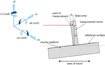
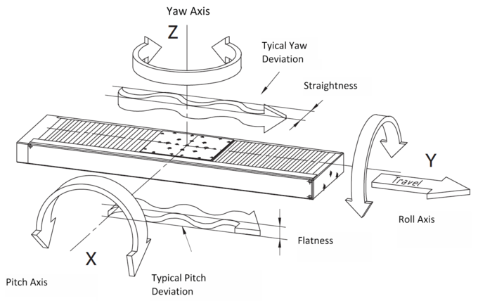
- Angular deviations: Pitch, roll, and yaw can introduce additional positioning errors.
- Integration effects: Mounting, mechanical support, and payload can alter stage behavior.
- Abbe errors: Angular deviations create additional positioning errors when the measurement reference and working point are separated.
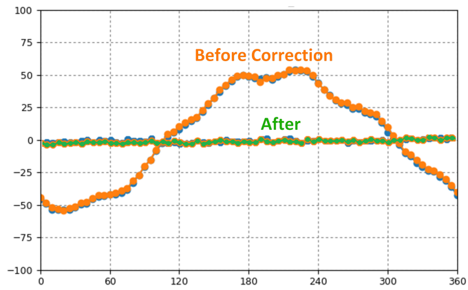
These effects are particularly important in multi-axis machining, metrology, inspection, and other processes that depend on accurate positioning throughout an XY working area. An example presented during the webinar illustrates the limitations of calibrating a stage independently. A screw-driven linear stage initially exhibited an accuracy of 25.8µm. After 1D calibration, the accuracy improved significantly to 7.3µm, as seen in the image above.
The same stage was then mounted on top of another stage to increase its height and make it behave more like a Y-axis in a stacked configuration. In this arrangement, the uncalibrated error increased to 37µm. Recalibration reduced the error to 8.1µm, as seen in the image above.
The results show that calibration accuracy depends on the actual mechanical configuration, load, mounting arrangement, and measurement conditions. A correction table generated for an individual stage may, therefore, have limited transferability once that stage is integrated into a larger machine.
2D Calibration Measures the Complete XY Working Area
Instead of measuring positioning errors along two independent lines, 2D calibration evaluates the complete XY workspace.
The 2D calibration system moves through a defined measurement grid while the actual positions are recorded and compared with the commanded positions. This produces a two-dimensional error map that describes the positioning deviations across the working area.
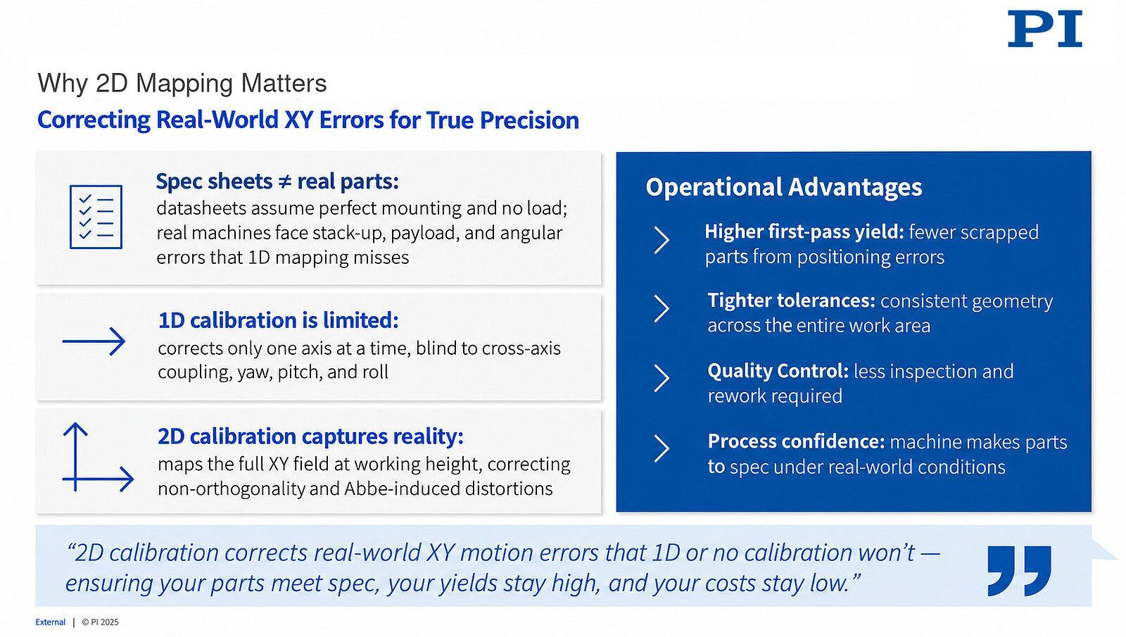
The correction data is stored in the motion controller, which interpolates between the measured grid points during operation. Modern motion controllers that support two-dimensional error correction can, therefore, compensate for systematic deviations throughout the XY workspace. The important distinction is that the calibration represents the behavior of the assembled XY system rather than that of two independent stages.
This allows the correction process to account more effectively for orthogonality errors, cross-axis interactions, integration effects, and other systematic deviations that conventional 1D mapping cannot adequately capture.
Traditional non-recirculating crossed-roller bearings also have practical limits on travel range and cage migration may be an issue with repetitive motion.
Measurement Results: From 50µm to 2.5µm
To demonstrate the effectiveness of 2D calibration, PI engineers evaluated several positioning technologies.
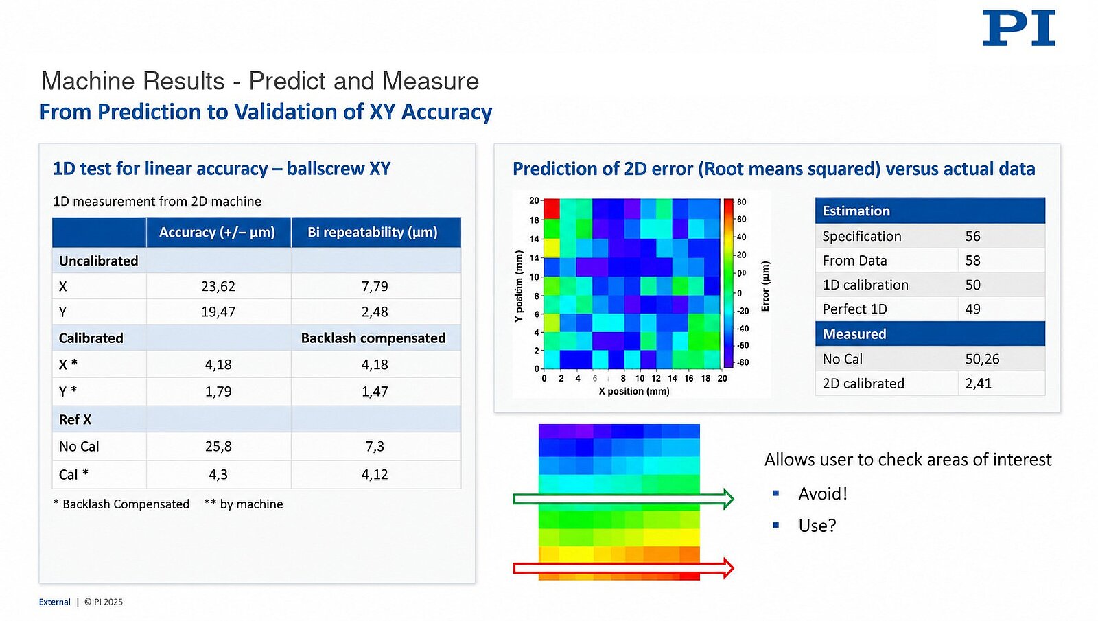
One experiment involved an XY system assembled from lower-specification screw-driven linear stages. The uncalibrated system exhibited approximately 50µm of two-dimensional positioning error. After automated 2D calibration, the measured error decreased to approximately 2.5µm.
This corresponds to an approximately 95% reduction in measured positioning error, achieved through 2D calibration, without replacing the mechanical stages.
Full-area mapping can provide additional benefits: the resulting error map shows regions of higher and lower positioning accuracy within the XY workspace. If an application has different accuracy requirements across its working area, this information can help engineers reserve the best-performing regions for critical processes. Areas with larger deviations may still be suitable for less demanding operations, such as loading or unloading.
Calibration Cannot Replace Mechanical Performance
Calibration can correct repeatable, systematic errors, but it cannot eliminate the fundamental mechanical limitations of a positioning system. Repeatability is particularly important because a correction table can only compensate for an error that occurs consistently. Random deviations, changing backlash, thermal drift, wear, and other nonrepeatable effects are much more difficult to correct.
Stage repeatability, friction, backlash, structural stability, duty cycle, and thermal behavior, therefore, continue to determine the achievable positioning performance. This is particularly relevant when comparing ball-screw-driven stages with direct-drive linear motor stages.
Ball-screw stages can provide good performance in point-to-point applications, particularly at moderate speeds and duty cycles. However, backlash compensation can change over time, and wear can affect long-term behavior. At higher operating speeds, heat generated in the screw can cause thermal expansion and additional positioning deviations. The system may also require a warm-up period before reaching stable operating conditions.
Direct-drive linear motor stages avoid the mechanical screw transmission. When combined with linear encoders, they provide direct position feedback, lower friction, and reliable motion during frequent directional reversals. These characteristics make them well suited to high-speed positioning and complex contouring applications.
Direct-Drive Stages: Submicron Error After Calibration
Results from an XY system based on direct-drive linear motor stages were also presented. Before 2D calibration, the system exhibited a two-dimensional positioning error of approximately 8.72µm. After calibration, the measured error was reduced to below 1µm, as seen in the image below.

A customer-performed measurement, using a two-dimensional coordinate measuring machine, provided an additional comparison. With the correction mapping switched off, the customer measured an error of approximately 11µm. PI’s corresponding measurement indicated a value close to 12µm. With the 2D correction enabled, the customer measured 0.82µm, compared with PI’s value of 0.94µm before delivery of that particular system.

The close correspondence between the two measurement methods provided additional confirmation of the corrected positioning performance. These results demonstrate how precision stage design and two-dimensional calibration complement one another.
Measurement Example | Before 2D Calibration | After 2D Calibration |
Lower-specification ball-screw XY system | ~ 50µm | ~ 2.5µm |
Direct-drive linear-motor XY system | ~ 8.72µm | < 1µm |
Customer-measured XY system, using a 2D CMM | ~ 11µm | ~ 0.82µm |
Planar XY stage | ~ 13.4µm | ~ 0.41µm |
The above results are application-specific measurement examples and should not be interpreted as universal stage specifications or guaranteed values for other configurations.
Integrated XY Stages: Why Mechanical Design Still Matters
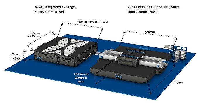
Another test compared a conventional stacked XY system with a compact integrated XY stage.
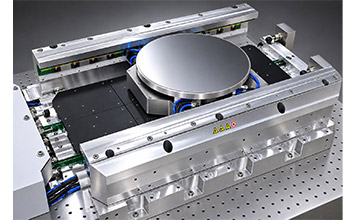
Integrated, 3-plane XY stages (often called planar stages) integrate both motion axes within a single mechanical structure. This can provide advantages in compactness, stiffness, load capacity, and geometric stability. The planar stage discussed in the webinar also used crossed-roller bearings, while the stacked system used ball-bearing-based mechanical stages.

Despite its more integrated mechanical design, the V-731 planar stage, initially, exhibited a larger uncalibrated positioning error than the stacked system: approximately 13.4µm compared with 9.2µm, respectively. After 2D calibration, however, the planar stage achieved a positioning error of approximately 0.41µm.
The explanation lies in repeatability. Even relatively large systematic geometric errors can be compensated for when they remain consistent from one measurement to the next. Random deviations, changing backlash, thermal drift, and other nonrepeatable effects cannot be corrected as effectively. The ultimate accuracy achievable through calibration is, therefore, closely linked to the repeatability of the complete mechanical system.
Automated Calibration Makes 2D Mapping Practical for Production
High-accuracy two-dimensional metrology can require substantial measurement time, specialized equipment, and careful setup.
PI engineers remarked that measuring a comparable XY system with a two-dimensional coordinate measuring machine could take considerable time, adding significant cost to the system. In addition to the measurement time, such a process can occupy specialized equipment and require support from trained metrology personnel.

PI developed an automated 2D metrology process to make full-area calibration more practical. The system measures positioning deviations throughout the XY working area, generates the required correction data, and enables the resulting error map to be applied through the motion controller.
It was stated that the measurement procedure is based on ISO 230 methodology. Because the speakers noted that no directly recognized 2D standard exists for this particular mapping procedure, PI’s metrology engineers adapted the ISO 230 approach for two-dimensional evaluation.
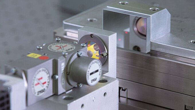
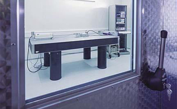
The automated equipment uses a high-resolution 2D scale to measure positioning deviations throughout the XY workspace. For the example presented, the automated process reduced the measurement time significantly, with everything optimized down to two hours.
Automation also reduces repeated manual setup, enables unattended measurement runs, and improves consistency between calibrations. This makes comprehensive XY calibration practical not only for custom high-end systems, but also for configurable standard motion products.
Example: 2D Calibration of a Configurable XY Motion System
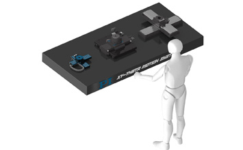
PI demonstrated the calibration process using a configurable multi-axis motion system (IMAS) based on direct-drive linear stages.
The system can be supplied as a fully assembled, tested, and tuned XY configuration. Depending on the application, it can also include granite mounting structures, additional vertical or rotary axes, and different performance classes. In the demonstrated configuration, engineers measured a working area of 300×200mm, using a grid with points spaced at 10mm intervals. Before calibration, the measured positioning deviations ranged from approximately −9µm to +7µm.
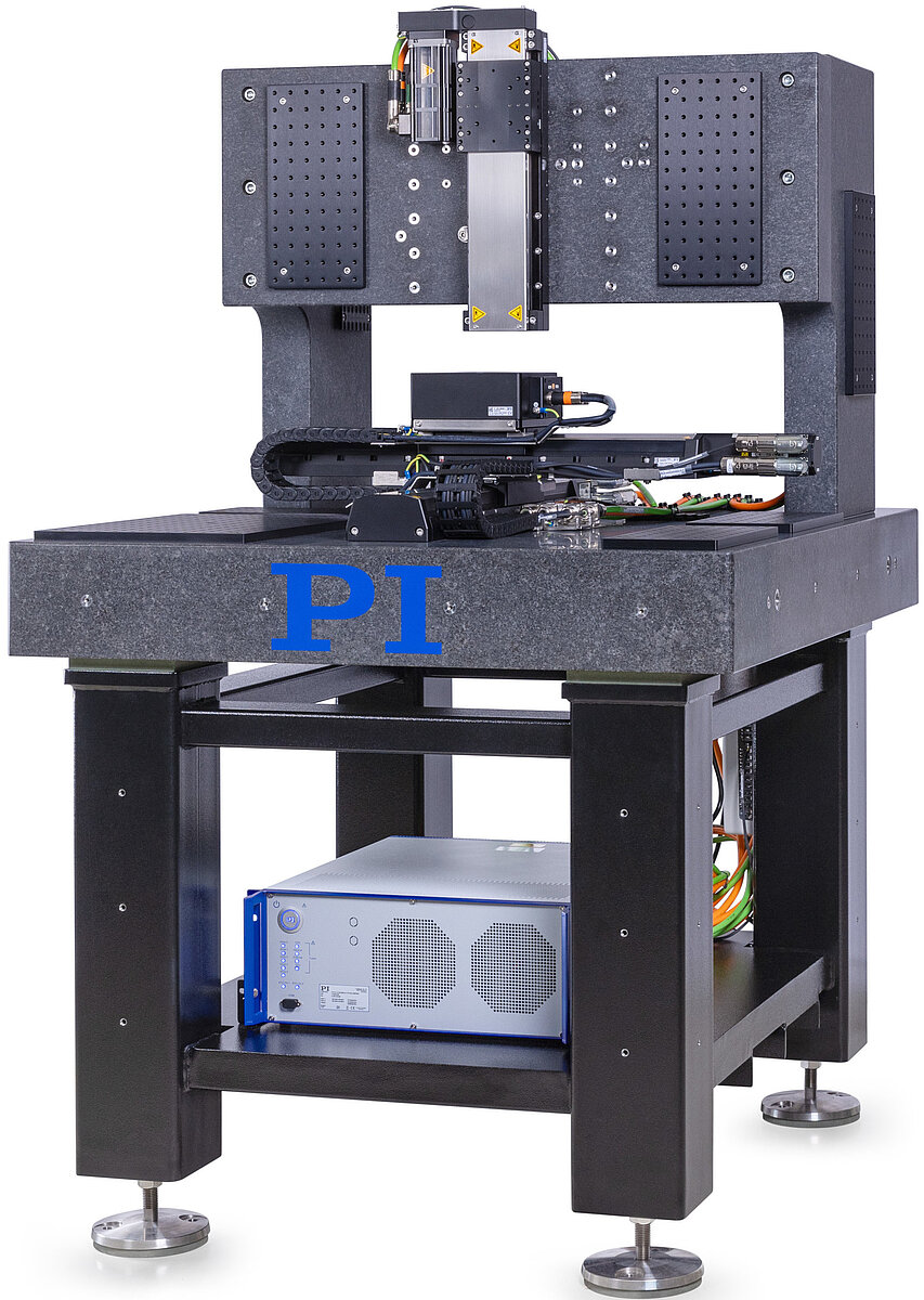
The correction values obtained during the initial measurement were then stored in the motion controller. After 2D mapping and correction, the measured deviations decreased to approximately −0.5µm to +0.7µm, across the working area.
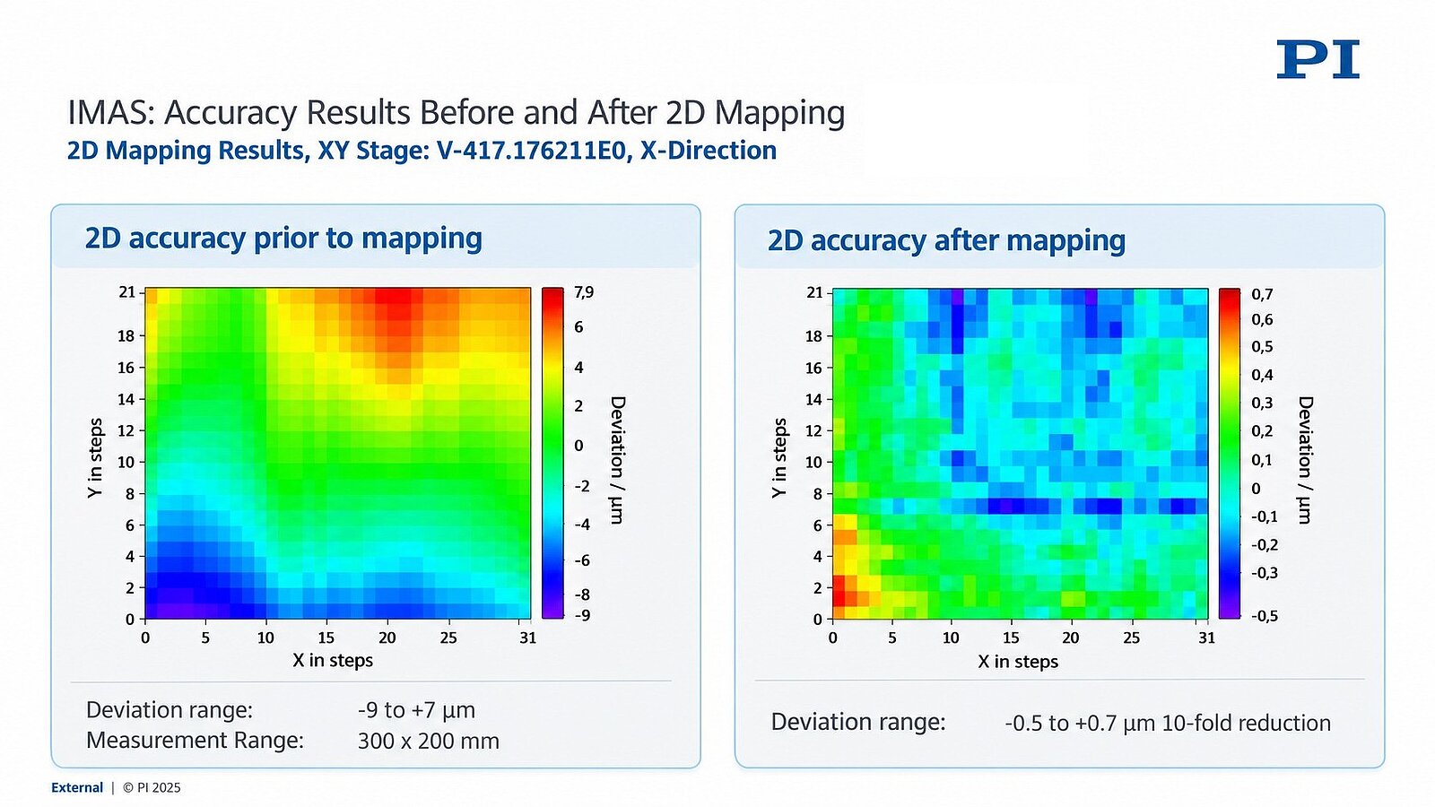
The measurement followed a meandering pattern through the complete XY area. The speakers also described that repeated measurements were performed to evaluate the stability of the corrected results. The deviation between the individual measurement runs remained significantly below 1µm, consistent with the approximately 1µm repeatability of the stage configuration.
For machine builders, this approach offers a practical way to obtain an assembled, tested, tuned, and calibrated multi-axis subsystem without developing an equivalent metrology process in-house.
Calibration Must Reflect the Actual Application
Calibration results depend on operating and measurement conditions.
A system calibrated under one set of mechanical, thermal, or motion conditions may behave differently when those conditions change. Payload, mounting arrangement, motion profile, speed, duty cycle, and thermal conditions can all influence positioning accuracy. For demanding applications, the calibration procedure should, therefore, represent the intended operating environment as closely as practical.
This is particularly important when the system operates at high speed or follows demanding motion profiles. For example, sustained high-speed operation of a ball-screw stage can generate heat, resulting in thermal expansion and positioning changes (as previously stated).
The presenters noted that the automated measurement process can be adapted to better represent the motion profile of the intended application. This should be discussed when the application requires performance close to the repeatability limits of the positioning system.
Better Accuracy Without Automatically Requiring More Expensive Mechanics
Precision manufacturing often involves balancing positioning accuracy, throughput, equipment cost, and long-term stability. One approach to achieving tighter tolerances is to select increasingly precise motion components. However, the webinar results demonstrate that improved calibration of an existing mechanical system can sometimes deliver substantial accuracy gains without changing the stage hardware.
This does not mean that calibration can turn any sloppy stage into a high-performance positioning system. Mechanical repeatability, stiffness, dynamics, thermal stability, duty cycle, and long-term wear remain essential considerations. Instead, 2D calibration provides another engineering tool for optimizing the performance of the complete motion system.
By correcting repeatable geometric and integration-related errors, 2D calibration can support tighter manufacturing tolerances, higher first-pass yield, and more consistent process results. The approach is particularly relevant to applications involving multi-axis machining, precision inspection, metrology, contouring, and coordinated motion across a defined XY workspace.
Summary: From Individual Stage Specifications to Actual System Performance
A motion stage’s data sheet describes its performance under defined measurement conditions. The accuracy that matters to the machine builder, however, is the positioning accuracy achieved at the actual working point in the completed system.

Automated 2D calibration helps bridge that gap. By measuring and correcting the combined errors of an assembled XY system, it provides a more realistic representation of positioning performance than independent axis calibration alone. The results presented during this PI webinar included improvements from approximately 50µm to 2.5µm for a lower-specification ball-screw system, from 8.7µm to below 1µm for a direct-drive system, and from 13.4µm to 0.4µm for a planar stage.
These values are specific to the tested configurations, measurement conditions, and calibration procedures. They should not be interpreted as guaranteed results for every XY system. The underlying principle, however, applies broadly: when systematic errors are repeatable, measuring and correcting them across the complete XY working area can substantially improve positioning accuracy.
For engineers designing precision manufacturing and inspection equipment, the key question is no longer simply how accurately each individual axis moves. The more important question is how accurately the complete system positions the working point throughout its operating area.
Watch the Webinar: Unlocking Efficiency and Accuracy with 2D Calibration
Learn more about the measurement principles, calibration procedures, motion technologies, and practical examples discussed in this article.
Discuss Your Application with PI
Whether your application involves precision XY scanning, multi-axis motion, high-speed contouring, micromachining, inspection, or metrology, PI engineers can help evaluate the positioning accuracy, repeatability, mechanical configuration, and calibration approach required for your system.




Blog Categories
- Aero-Space
- Air Bearing Stages, Components, Systems
- Astronomy
- Automation, Nano-Automation
- Beamline Instrumentation
- Bio-Medical
- Hexapods
- Imaging & Microscopy
- Laser Machining, Processing
- Linear Actuators
- Linear Motor, Positioning System
- Metrology
- Microscopy
- Motorized Precision Positioners
- Multi-Axis Motion
- NanoAutomation
- Nanopositioning
- Photonics
- Piezo Actuators, Motors
- Piezo Mechanics
- Piezo Transducers / Sensors
- Precision Machining
- Semicon
- Software Tools
- UHV Positioning Stage
- Voice Coil Linear Actuator
- X-Ray Spectroscopy