As semiconductor devices continue to shrink and advanced packaging technologies become more complex, wafer inspection systems face growing demands for precision, throughput, and stability. Atomic force microscopy (AFM) remains one of the most powerful tools for nanoscale surface characterization, but achieving meaningful throughput requires motion systems capable of combining nanometer-level positioning accuracy with high scanning speed.
Traditional precision-positioning stage technologies often force designers to compromise. Mechanical bearings introduce friction, wear, and hysteresis, while air bearings require continuous airflow and can be challenging in ultra-clean or vacuum environments. Magnetic levitation (MagLev) technology offers an alternative approach by eliminating physical contact altogether.
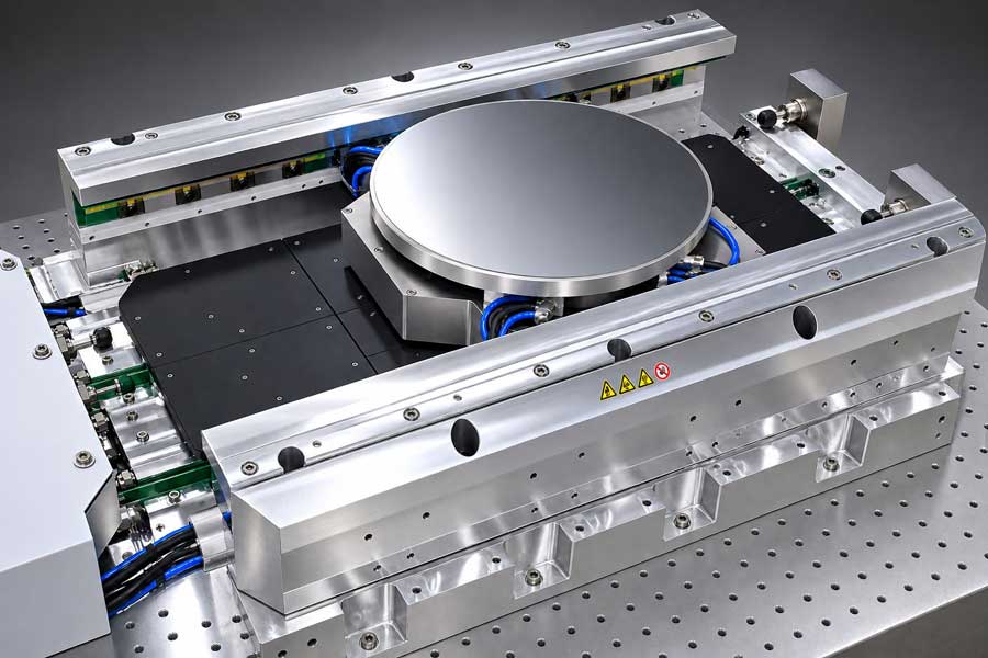
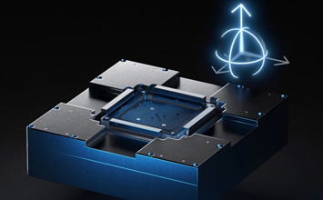
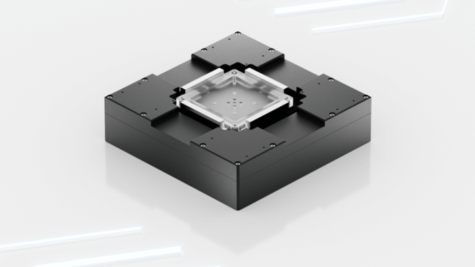
A research paper by PI R&D engineers explores how advanced simulation techniques can be used to design a next-generation planar magnetic levitation stage specifically optimized for AFM-based wafer inspection. The result is a conceptual 6-degree-of-freedom (6-DOF) platform designed to deliver both ultra-high precision and high dynamic performance while minimizing thermal effects that can degrade measurement accuracy.
This work builds on PI's broader research into magnetic levitation positioning systems, which demonstrates the potential of friction-free, actively controlled 6-DOF motion for nanopositioning and metrology applications. Existing research platforms already show how magnetic levitation can eliminate friction, wear, particle generation, and mechanical hysteresis while providing active control of all six degrees of freedom.
Why AFM Inspection Challenges Conventional Motion Systems
AFM wafer inspection places unique demands on motion control. The stage must scan rapidly across a semiconductor die while maintaining sub-nanometer stability under the probe. Any vibration, drift, angular error, or thermal distortion can directly impact measurement accuracy.
For this R&D project, the design targets were ambitious:
- 50 × 50 mm travel in X and Y
- 100 µm travel in Z
- 5 kg payload capacity
- Scanning speeds up to 100 mm/s
- Acceleration up to 500 mm/s²
- Less than 1 nm peak-to-peak jitter
- Less than 200 pm RMS positioning noise
Meeting these requirements simultaneously pushes conventional motion technologies to their limits. While AFM piezo flexure stages achieve sub-nanometer resolution, travel ranges are typically limited to below 1 mm.
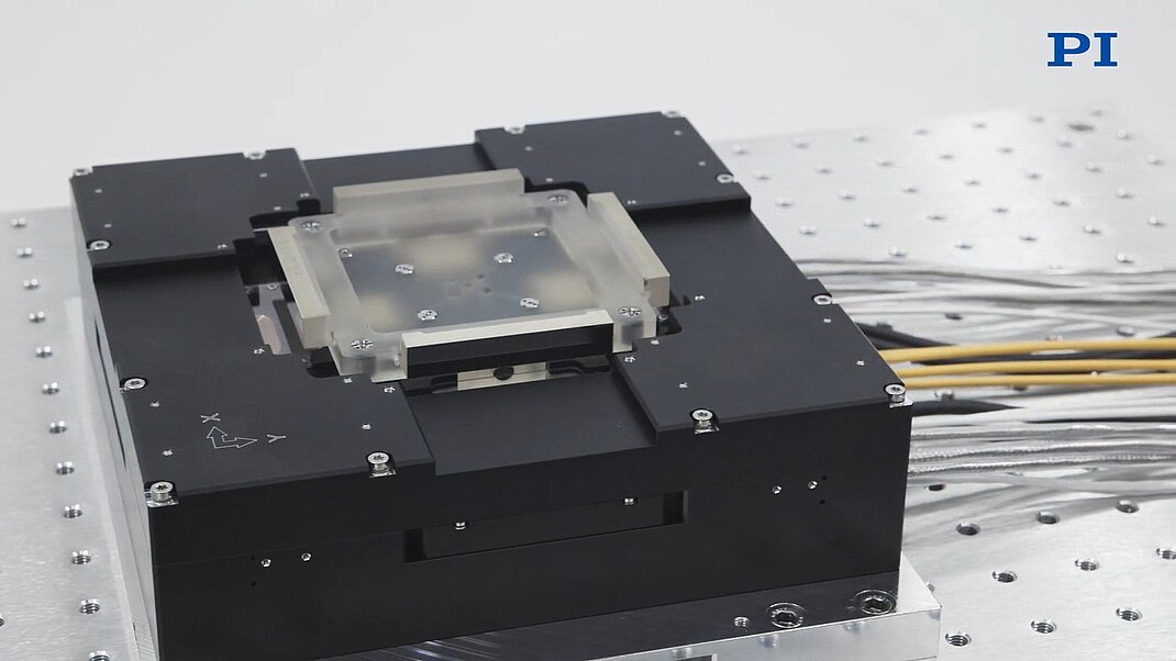
Magnetic levitation provides several inherent advantages. Because the mover is suspended entirely by electromagnetic forces, there is no contact between moving and stationary components. This eliminates friction, lubrication requirements, mechanical wear, and particle generation while allowing the system to operate in highly controlled environments.
Designing the System Through Mechatronic Simulation
One of the most important findings from the project is that MagLev stage development cannot be treated as a standalone motor-design exercise.
In conventional motion systems, motors, mechanics, sensors, and thermal management can often be optimized somewhat independently. Magnetic levitation systems are fundamentally different. Changes to one subsystem immediately influence the others.
For example, modifying the permanent magnet architecture affects mover mass and inertia. Changes in inertia influence the forces and torques required from the motors. Increased force requirements change power consumption and thermal behavior, which can then affect positioning stability.
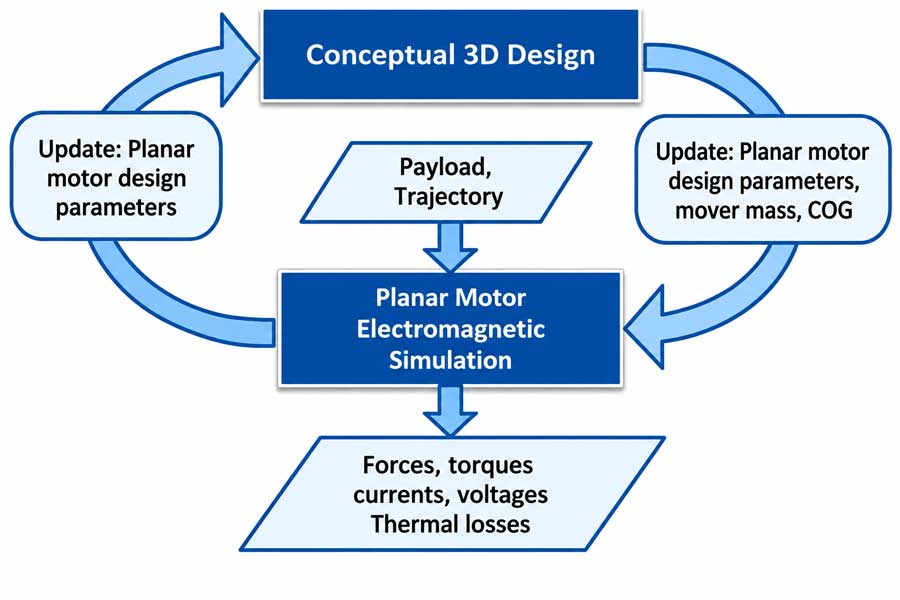
To address these interactions, the project employed an iterative mechatronic design workflow.
The process begins with a mechanical concept, payload requirements, and desired scanning trajectories. Mover mass properties are then integrated into an electromagnetic simulation model that predicts:
- Force generation
- Torque generation
- Coil currents
- Drive voltages
- Power dissipation
- Thermal behavior
Results from each simulation cycle are fed back into the design, allowing the mechanical and electromagnetic architectures to evolve together until performance objectives converge.
This simulation-driven development approach significantly reduces design risk while helping engineers identify performance bottlenecks before hardware is built.
Separating Motion Generation from Precision Metrology
The stage concept consists of a levitating mover and stationary stator; each divided into dedicated force-generation and metrology structures.
The overall platform measures approximately 580 × 580 × 82 mm and uses a mover with a mass of 14.3 kg prior to adding the 5 kg payload.
The metrology system directly measures all six degrees of freedom:
- Four laser encoders monitor X and Y translation as well as rotation about the Z-axis.
- Four laser interferometers measure Z position and angular motion around the X and Y axes.
- Integrated gratings and precision mirrors provide passive reference structures on the mover.
This architecture enables direct measurement rather than relying solely on motor commutation estimates, improving positioning accuracy and stability.
The separation between force generation and metrology structures also opens opportunities for future thermal isolation and structural optimization. Further studies are planned to evaluate whether compliant decoupling elements are required to minimize the transmission of thermal or mechanical disturbances between subsystems.
Ironless Planar Motors Enable Full 6-DOF Control
The motion platform uses four ironless planar motors arranged at 90-degree intervals.
Each motor incorporates permanent-magnet Halbach arrays, a highly efficient magnetic configuration frequently used in magnetic levitation applications to increase force density while minimizing stray magnetic fields. PI has previously highlighted the advantages of Halbach-based magnetic levitation architectures for precision positioning systems.
The motors operate according to the Lorentz-force principle and deliver highly linear force generation without the hysteresis often associated with iron-core motors.
The X-oriented motor pair primarily controls:
- X-axis motion
- Vertical Z force
- Rotation about X
The Y-oriented pair governs:
- Y-axis motion
- Vertical Z force
- Rotation about Y
Because all degrees of freedom are coupled, the system requires advanced multi-axis control. A proprietary electromagnetic simulation framework calculates the optimal current distribution across every coil based on real-time mover position and the desired six-dimensional force and torque command.
At the same time, the algorithm minimizes electrical losses while ensuring commanded motion does not create unwanted rotational disturbances.
Why Thermal Stability Matters More Than Total Power
For AFM inspection systems, thermal management is often just as important as positioning performance.
A stage may produce acceptable average heat levels but still introduce measurement errors if thermal loads vary significantly across the scan area. Position-dependent heating can create temperature gradients that distort structures and alter metrology measurements.
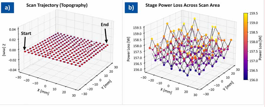
To evaluate this effect, the design team simulated a 15 × 15 grid meandering scan trajectory covering the full 50 × 50 mm2 operating area.
The results were encouraging.
At a nominal 2 mm air gap:
- Average power loss was approximately 157.4 W.
- Standard deviation across the full trajectory was just 0.8 W.
This small variation suggests highly uniform heat generation across the scanning envelope, reducing one potential source of thermally induced drift.
Reducing the air gap by 0.5 mm to 1.5 mm lowers the overall loss level by 23 W, while a vertical displacement of 100 μm leads to a small power consumption increase of only 4 W. Across the full X-Y travel range, the loss variation remains small.
The stability of the losses across variations supports the robustness of the design.
High-Speed Scanning Without a Thermal Penalty
One concern with high-speed AFM motion is the additional power required for acceleration and deceleration.
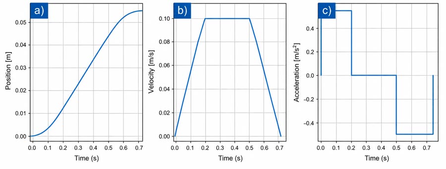
To investigate this effect, dynamic simulations were conducted using 100 mm/s scanning velocity and 0.5 m/s² acceleration profiles.
Surprisingly, the additional motion demand had very little impact on overall power consumption.
Average dissipation increased by only about 1.2 W compared with the quasi-static case, while motor requirements remained below 22 V and 1.7 A.
For system designers, this is a significant result. It suggests that achieving higher throughput does not necessarily require a proportional increase in thermal load, removing a common tradeoff between speed and stability.
Liquid Cooling Provides a Practical Solution
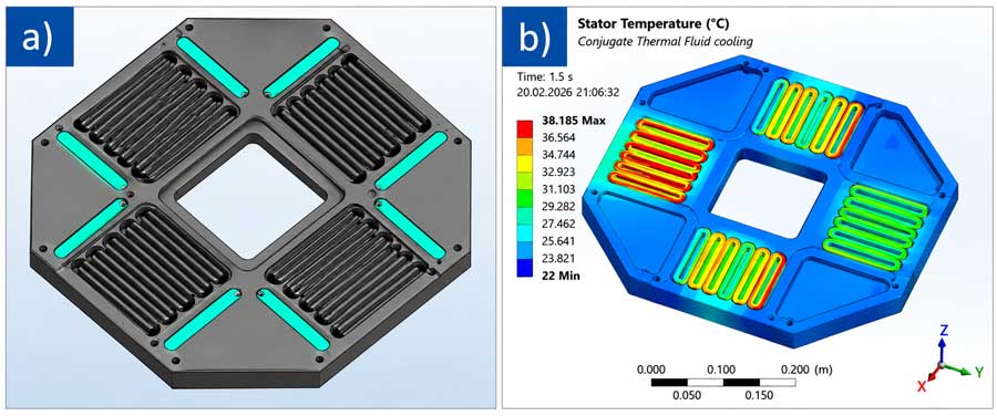
Although thermal losses are relatively uniform, approximately 160 W of dissipation still must be managed effectively. Thermal finite-element simulations compared passive cooling with liquid-cooled designs incorporating cooling channels beneath the motor arrays.
Without active cooling, simulated hot spots reached 56.7 °C. Introducing a modest coolant flow of only 0.2 l/min reduced the peak temperature to 38.4 °C, an improvement of roughly 18 K. Further increases in flow rate provided only marginal benefits, indicating that moderate liquid cooling is sufficient to maintain thermal stability while avoiding excessive system complexity.
The Future of Simulation-Driven MagLev Systems
The project highlights an important trend in precision motion engineering: success increasingly depends on system-level optimization rather than individual component performance. For magnetic levitation stages, the mechanical structure, electromagnetic design, sensor architecture, thermal management, and control algorithms must all be developed together.
Future work will include:
- Structural modal analysis
- Thermal-strain modeling
- Evaluation of ultra-low-expansion materials, such as Zerodur, silicon carbide, and aluminum nitride
- Further optimization of the commutation algorithm to minimize spatial variations in power dissipation
As semiconductor manufacturers push toward ever-higher throughput and tighter dimensional tolerances, these integrated design approaches will become increasingly important.
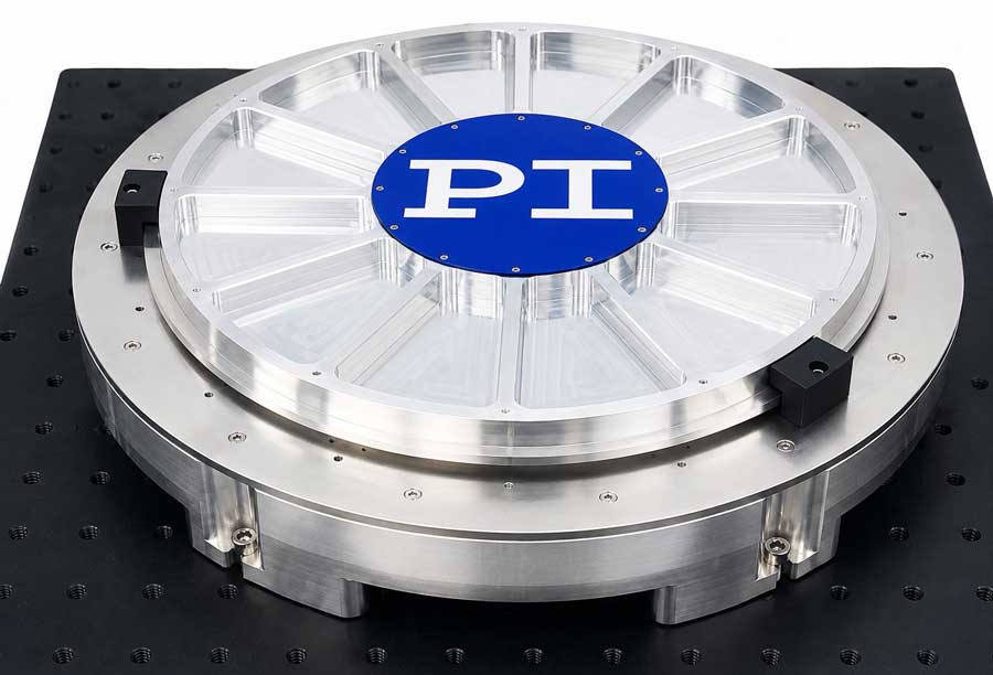
Magnetic levitation technology offers a compelling path forward, combining friction-free motion, active 6-DOF control, nanometer-scale precision, and excellent thermal stability. When paired with advanced simulation tools, it enables engineers to explore and optimize complex interactions long before hardware exists, accelerating development and reducing design risk.
For wafer inspection and AFM metrology, that combination may prove essential in meeting the next generation of semiconductor manufacturing challenges.
Download precision motion stages for semiconductor test & manufacturing brochure
» Read the full PDF paper by Daniel Geißler, Arne Feldkamp, Rudolf Krüger
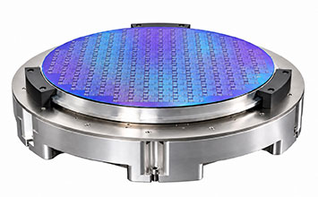
Award-Winning MagLev / Surface Shaping Poster at SEMICON West
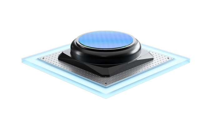
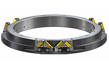
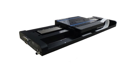
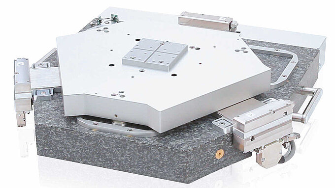
PI’s award-winning poster at SEMICON West 2026 highlighted MagLev wafer-stage platforms for linear and rotary motion as well as Active Wafer Chuck technology for advanced semiconductor manufacturing. Contact-free MagLev motion combines long travel, nanometer-scale stability, and six-axis control, while piezo-based active wafer shaping compensates for wafer bow, warp, and local deformation. Together, these technologies address positioning, throughput, and substrate flatness challenges in hybrid bonding, inspection, and metrology.






Blog Categories
- Aero-Space
- Air Bearing Stages, Components, Systems
- Astronomy
- Automation, Nano-Automation
- Beamline Instrumentation
- Bio-Medical
- Hexapods
- Imaging & Microscopy
- Laser Machining, Processing
- Linear Actuators
- Linear Motor, Positioning System
- Metrology
- Microscopy
- Motorized Precision Positioners
- Multi-Axis Motion
- NanoAutomation
- Nanopositioning
- Photonics
- Piezo Actuators, Motors
- Piezo Mechanics
- Piezo Transducers / Sensors
- Precision Machining
- Semicon
- Software Tools
- UHV Positioning Stage
- Voice Coil Linear Actuator
- X-Ray Spectroscopy