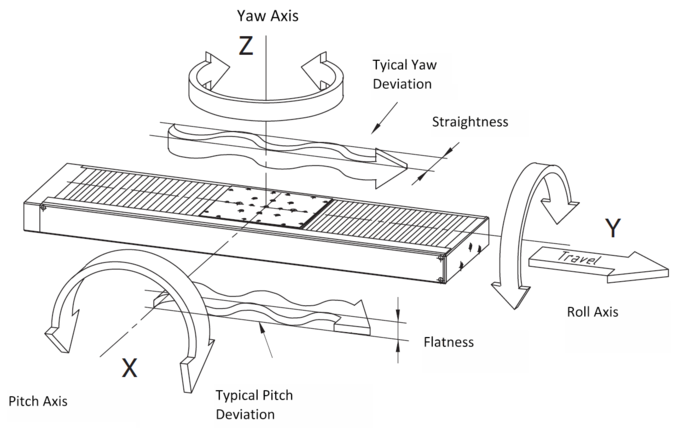
Six distance channels and a mirror cube capture translation, rotation, and unwanted motion in a single quasi-static measurement. A positioning stage does not move only along its commanded axis. Its motion can also include lateral displacement and rotations. A conventional single-axis measurement characterizes one component of this motion but does not provide a complete picture of how the platform behaves.
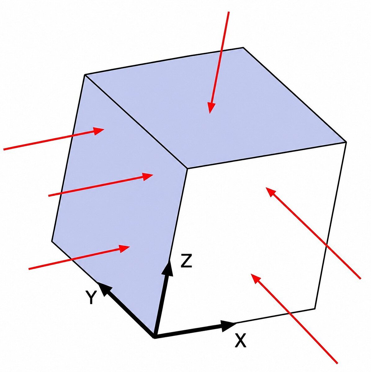
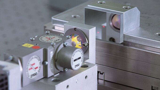
Researchers at PI developed a modular interferometric measurement setup that determines motion in all six degrees of freedom (6-DoF) from six distance measurements. Compact fiber interferometer heads are directed at three faces of a mirror cube mounted on the moving stage. Two versions of the system were built: a compact setup for short-stroke piezo stages and a larger arrangement for positioning systems with longer travel ranges.
Six Beams, Three Mirror Surfaces
The measurement arrangement uses three beams in the X direction, two in Y, and one in Z. The six distance measurements provide the information required to calculate three translations and three rotations. Differential measurements between beams directed at the same mirror surface provide angular information. Using fiber-based interferometers makes the arrangement compact and allows the sensor heads to be positioned close together. At the beginning of the project, three-channel quDIS fiber interferometers from qutools were available. A later setup containing two PI Range Resolved Interferometers (PIRRI) produced comparable results. The numerical reference comparisons presented here are for the quDIS setup.
Sensor Spacing Sets a Resolution and Travel Tradeoff
Sensor spacing plays an important role in angular measurement. For a given angular movement, two beams separated by a greater distance produce a larger differential displacement signal. Increasing this separation, therefore, improves the achievable angular resolution.

At the same time, greater sensor spacing reduces the usable travel across a finite mirror surface. For this system, the researchers selected a spacing of 20.5 mm between the fiber heads as a compromise between angular resolution, available stroke, and mirror size. The maximum stroke is limited by the cube's edge length minus the separation between the sensor heads.
The two setups use solid glass mirror cubes with edge lengths of 30mm and 100mm. The mirror surfaces are specified with an orthogonality of 2 arcsec and a flatness of λ/10 at 1530nm. Because surface flatness and orthogonality are directly connected to measurement precision, the mirror cube is an important part of the metrology system. There is also a mechanical trade-off. The larger glass cube weighs approximately 2.5kg, a load that must be considered when assessing the stage's payload capacity and the conditions under which the stage is characterized.
A Modular Sensor Frame
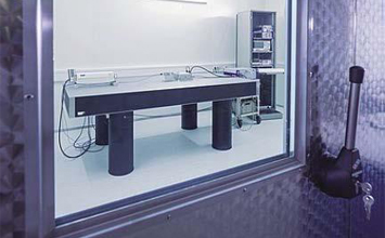
The stage under test is mounted on a vibration-isolated optical table, with the mirror cube attached to the moving platform. Aw separate holder carries the individual interferometer heads. Each head can be adjusted independently in axial position and in two angular directions relative to the mirror surface. The design combines individual sensor alignment with the ability to reposition the complete sensor assembly as an aligned unit. Construction rails provide additional flexibility for accommodating stages with different dimensions and travel ranges.
This mechanical concept allows the aligned sensor assembly to be transferred between stages without rebuilding or fully recalibrating the optical arrangement. However, the sensor coordinates relative to the pivot point still need to be determined for the stage-specific 6-DoF calculation.
Converting Six Distance Signals into a 6-DoF Pose
Reconstructing the platform pose requires knowing the positions of the measurement beams relative to the system's pivot point. Because the setup is designed to work with different positioning systems, these coordinates cannot simply be taken from a fixed CAD model. Instead, the researchers determined them experimentally.
Small rotational movements are applied while an external reference instrument measures the corresponding angle. Under the small-angle approximation, the distance of a beam from the pivot point can be calculated.
The calibrated beam coordinates are then combined with the six interferometer distance signals. The rotational components are determined first, followed by the translational coordinates, resulting in the complete X, Y, Z, θx, θy, θz pose.
Short-Stroke Comparison with a Reference Measurement System
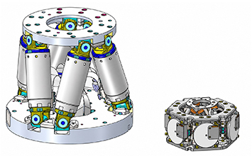
The compact configuration was demonstrated on a P-562.6CD 6-axis piezo positioning system using the 30mm mirror cube.
The setup has an angular acceptance of approximately ±34mrad, which is sufficient for the typical motion range of piezo-flexure based flexure nanopositioning systems. The Y-axis measurement covered the full stage stroke using five repetitions, with 20 measurement points on each forward and backward path.
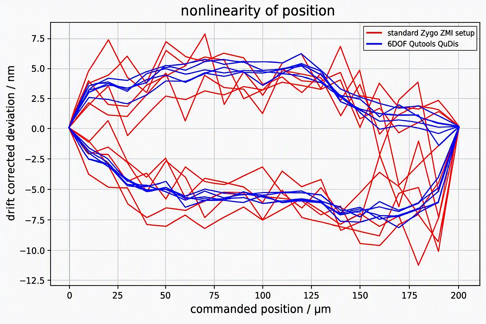
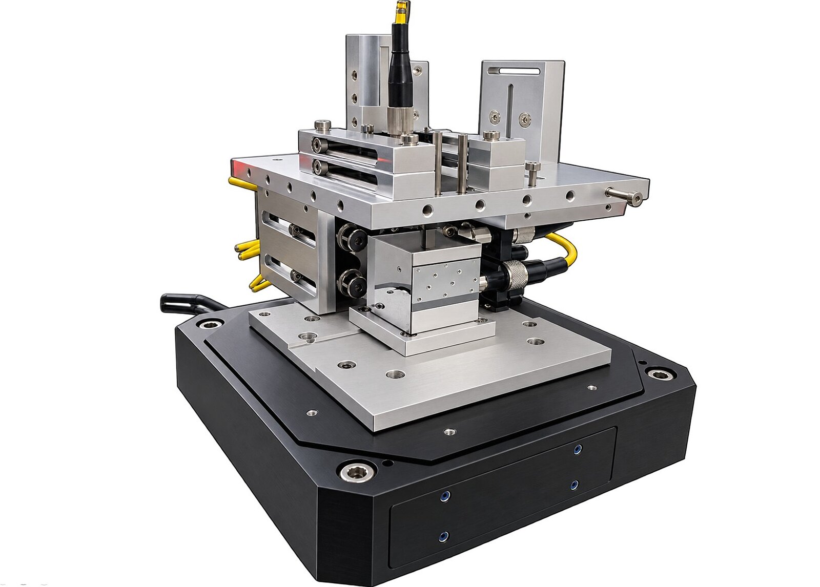
Measurements were performed quasi-statically and nearly simultaneously with the 6-DoF system and a reference setup consisting of a Zygo ZMI interferometer and an autocollimator.
Short-Stroke Measurement Results
| Reported Stage Parameter | Zygo ZMI Reference | quDIS 6-DoF Setup |
| Bidirectional accuracy | 16.6 nm | 25.9 nm |
| Unidirectional repeatability | ±1.7 nm | ±0.4 nm |
| Stroke | 200.005 µm | 200.025 µm |
| Linearity | 5.2 nm | 5.3 nm |
Parameters calculated for the stage from each measurement system, not stand-alone accuracy specifications for the interferometers.
The measured strokes differ by only 0.020µm, or 20nm, corresponding to approximately 0.01% of the reference stroke. The bidirectional accuracy values differ by 9.3nm.
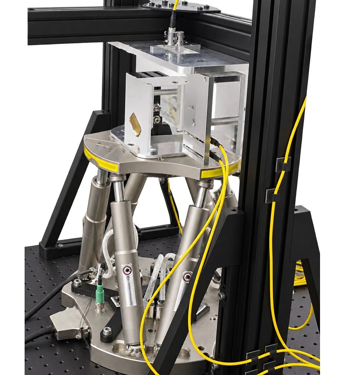
Differences between the two measurement systems are less than 0.05% relative to the travel path. This statement refers to differences normalized to the stage travel and should not be interpreted as percentage agreement between the individual accuracy or repeatability values. For systems requiring greater travel ranges, the researchers are now setting up a second configuration using the 100mm mirror cube. This arrangement supports motion ranges up to 75mm in X, Y, and Z.
All 6-DOF Motion Components in One Measurement
The main advantage of the new approach is its ability to characterize the commanded movement and accompanying motion components in a single quasi-static measurement.
The reference measurements show strong correlation between the 6-DoF interferometer arrangement and established single-axis reference systems. At the same time, the six-channel setup provides additional information about motion in the other degrees of freedom. This is particularly useful when characterizing high-precision positioning stages and parallel-kinematic systems, where lateral and angular motion can be important parts of the overall positioning behavior. Future developments could extend the technique into dynamic measurements, larger rotation angles, and further automation.
Work with Metrology Experts
Whether your application involves 6-axis motion or high-speed single-axis scanning, PI engineers can help evaluate the mechanical configuration needed to achieve your project’s goals for positioning resolution, repeatability, accuracy, and dynamic performance.




Blog Categories
- Aero-Space
- Air Bearing Stages, Components, Systems
- Astronomy
- Automation, Nano-Automation
- Beamline Instrumentation
- Bio-Medical
- Hexapods
- Imaging & Microscopy
- Laser Machining, Processing
- Linear Actuators
- Linear Motor, Positioning System
- Metrology
- Microscopy
- Motorized Precision Positioners
- Multi-Axis Motion
- NanoAutomation
- Nanopositioning
- Photonics
- Piezo Actuators, Motors
- Piezo Mechanics
- Piezo Transducers / Sensors
- Precision Machining
- Semicon
- Software Tools
- UHV Positioning Stage
- Voice Coil Linear Actuator
- X-Ray Spectroscopy