Application Description
Most of the motion solutions we work on typically require either point-to-point positioning or constant velocity scanning motion. In these applications, customers are usually concerned with accuracy, repeatability, or velocity regulation.
One special type of motion that is occasionally required is sinusoidal scanning motion. In these applications, the motion stage is expected to oscillate back and forth at a certain displacement and frequency. In these applications, customers are concerned with following error – which is the system’s ability to follow the commanded motion trajectory.
Sine scanning is common in the optics world, where actuators, like galvanometers, oscillate mirrors and lenses at several kHz. However, the motion created by such systems is rotational. For customers who want to create true linear motion, a different technology must be used.
Travel
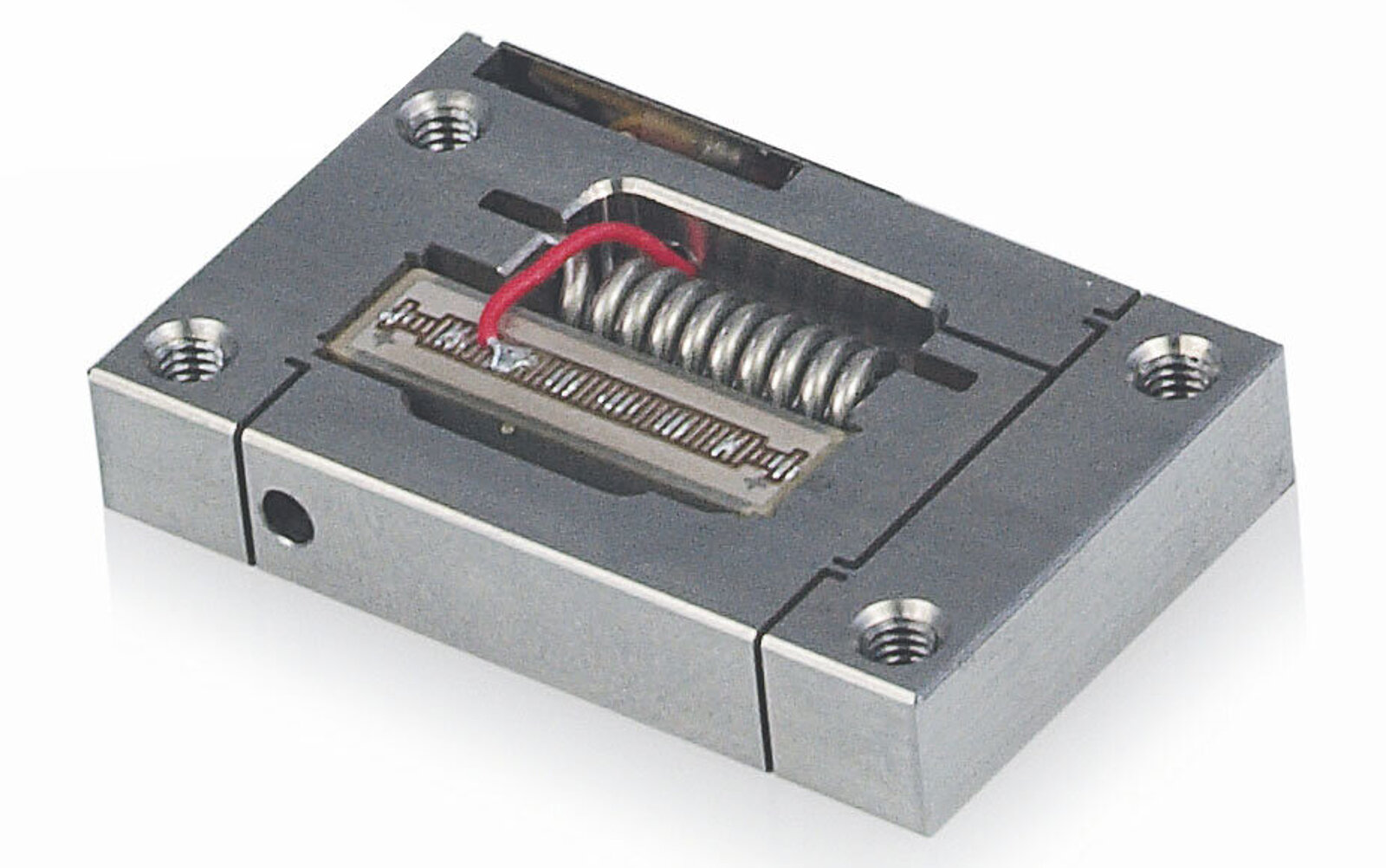
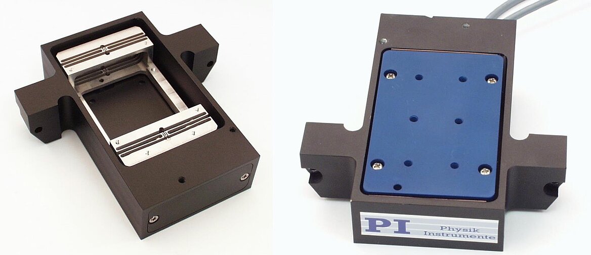
Piezo-actuated flexure stages are the most common type of product used to create highly precise linear sine scan motion at high frequencies up to the kHz range. PI offers a wide array of products suited to this type of motion. However, these products are limited to travel ranges of less than 2 mm. For travel ranges longer than a few millimeters, different drive types and linear bearings must be used. Should mechanical bearings be selected, or are air bearings a better choice?
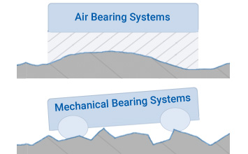
Mechanical Bearings vs. Air Bearings
Air bearings provide superior scanning performance when compared to mechanical technologies for one main reason: air bearings have no friction. An air bearing has no physical contact between moving parts and floats on a cushion of air. Thus, air bearings do not need to overcome dynamic friction to maintain tight velocity regulation. Best of all, the bearing won’t heat up due to friction and will never wear out.
All mechanical bearings exhibit some level of static and dynamic friction that must be overcome by the drive and control system. Friction levels can change with temperature, lubrication, preload, speed, payload, and wear. This makes friction behave in unpredictable and non-linear ways, and friction levels can vary widely from unit to unit. Over time, mechanical bearings wear down and lubrication properties break down. Under high duty cycles, bearings can heat up and cause problems with accuracy, preloading, and lubrication.
Motor Types and Power
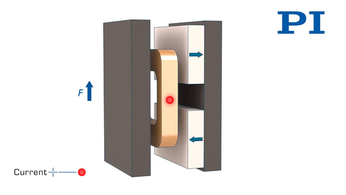
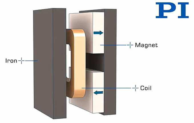
In order to achieve the speeds and accelerations needed for sine scanning motion, a properly-sized direct-drive solution is necessary; in this case, a voice coil or a 3-phase linear motor. Voice coils work well for travel lengths up to 25mm and do not require 3-phase motor commutation. For travels longer than 25mm, a 3-phase linear motor is the recommended solution.
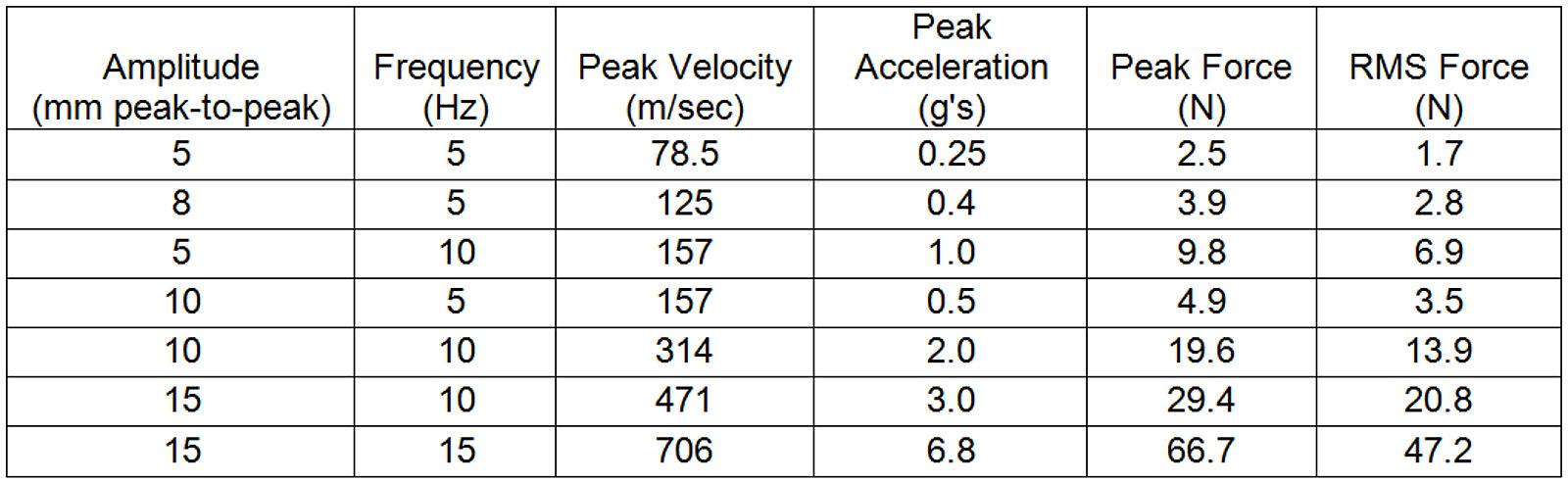
We need a motor that can continuously drive the system at the RMS force, assuming that the sine scan motion needs to be made continuously for durations lasting longer than a few seconds.
Assuming that we have designed a stage with a sufficiently powerful motor and small enough moving mass, we must choose a controller and servo drive capable of delivering the necessary power to the stage. However, keep in mind that not all control systems of equal power will perform the same. Many other factors, such as processing speed, servo loop bandwidth, feedback noise, servo loop gains, and control algorithms, play a role as well. For peak performance, select a control system that is designed to operate high speed, ultra-precise motions systems. For many systems, we use the SPiiPlusEC controller from ACS.
Following Error Performance
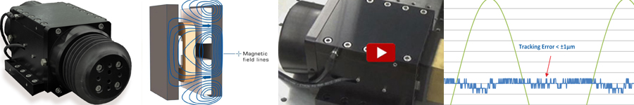
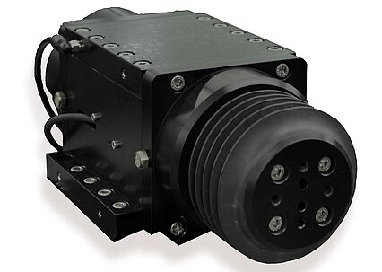
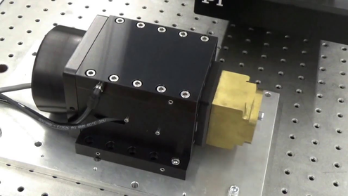
The product we tested was the PIglide A-131 with 25mm of travel. The stage features a direct-drive voice coil motor, optical linear encoder, and a fully preloaded 4-sided air bearing design. The motor coil and encoder read head are stationary, eliminating the need for any moving cable loops.
The blue line represents the following error of the A-131 air bearing stage performing the move profile indicated by the green line. When commanded to scan 8mm peak-to-peak at 5 Hz, the air bearing stage tracking error was under +/-1µm during the scan.
In a future post, we will compare the measured performance of this stage to a mechanical bearing linear motor stage.
Contact us today at air@pi-usa.us to discuss how we can solve your precision motion challenge.


Blog Categories
- Aero-Space
- Air Bearing Stages, Components, Systems
- Astronomy
- Automation, Nano-Automation
- Beamline Instrumentation
- Bio-Medical
- Hexapods
- Imaging & Microscopy
- Laser Machining, Processing
- Linear Actuators
- Linear Motor, Positioning System
- Metrology
- Microscopy
- Motorized Precision Positioners
- Multi-Axis Motion
- Nanopositioning
- Photonics
- Piezo Actuators, Motors
- Piezo Mechanics
- Piezo Transducers / Sensors
- Precision Machining
- Semicon
- Software Tools
- UHV Positioning Stage
- Voice Coil Linear Actuator
- X-Ray Spectroscopy