How Air Bearings Provide Better Straightness and Flatness
Setup, Definitions and Measurement of Linear Air Bearings and Stages
1. Introduction
When working with air bearings, we often describe the quality of motion as one of the key factors in selecting an air bearing; specifically, the straightness and flatness of travel of linear bearings and stages. Just how straight and flat? What levels of precision are achievable?
In this technical note, we will discuss several aspects: the error motion over full travel, impacts on error motion, the repeatability of the error, and the short-term errors.
2. Definitions: what is straightness and flatness?
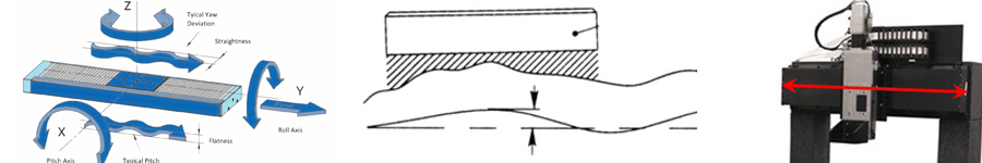
Define our coordinate system. See Figure 1. X = axis of motion for a linear stage.
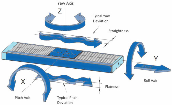
Straightness error motion (“straightness”) is defined as error motion in the Y direction. As the stage travels along the X axis, the motion deviates from the perfect line by some amount.
Flatness error motion (“flatness”) is defined as error motion in the Z direction. As the stage travels along the X axis, the motion deviates from the perfect line by some amount.
3. Error motion over full travel
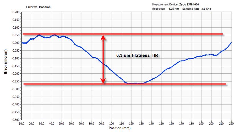
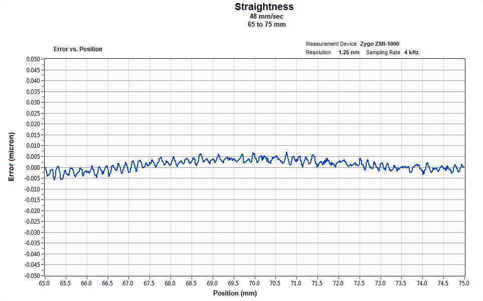
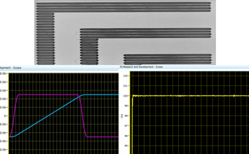
The first specification we discuss is the total error motion over full travel. This measurement is usually specified in “microns TIR.” TIR means Total Indicator Reading. When TIR is used, we are specifying the peak-to-peak measurement of error motion. We do not assume symmetry about a zero reference. In Figure 3, we see the straightness error plotted over 220mm of travel. The TIR reading is 0.3 µm. Air bearing stages can typically achieve better than 1 µm flatness and straightness TIR for every 200mm of travel. See detailed product spec sheets for actual specifications.
4. Error motion impacts
Besides the inherent quality of the stage or bearing itself, straightness and flatness error motions of air bearings can be affected by several outside influences.

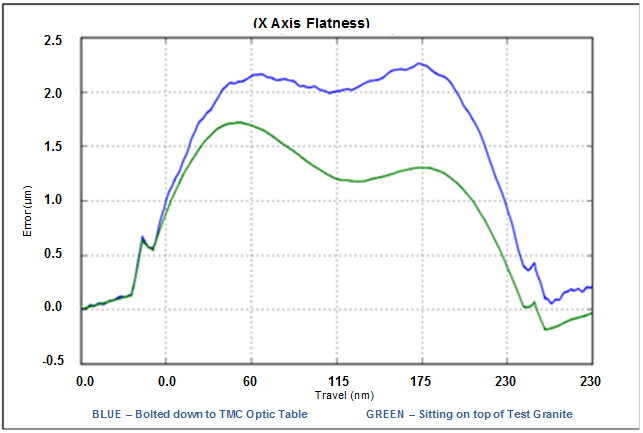
4.1 Quality of the mounting surface
Air bearing stages require a very rigid, clean, flat surface for mounting. Any irregularity in the surface, debris, burrs, or dirt, can have a noticeable impact on the stage’s error motion, particularly flatness. In Figure 4, we see the difference in flatness for a stage mounted to granite surface plate of high quality vs. mounted to an optical breadboard. The breadboard mounting adds a full micron of flatness error motion to the stage.
4.2 Length of travel
Since air bearing precision is in many ways a function of machining and grinding tolerances, which are inherently harder to hold over larger surfaces, longer travel stages will often have larger straightness and flatness error motions than shorter travel stages.
4.3 Size of stage
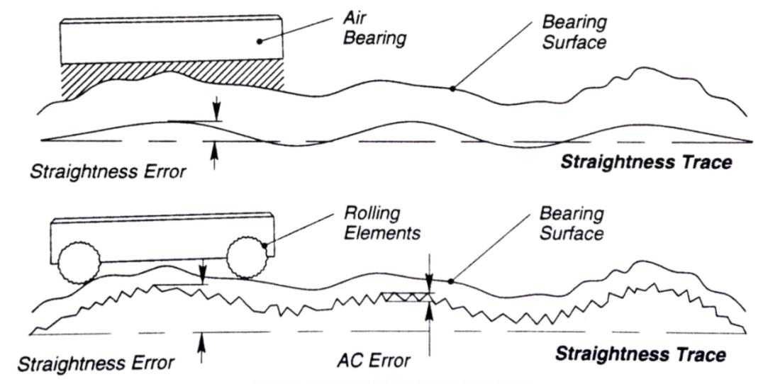
Stages with a larger footprint or with a larger separation between bearing surfaces will usually have smaller straightness and flatness error motions than a smaller-sized stage. Greater separation between bearing surfaces allows angular errors to translate into smaller lateral errors. Larger bearing surfaces increase the averaging effect (see Figure 5) of air bearings and reduce the error motions.
4.4 External perturbations
As with any measure of ultra-precision, air bearing stages can have their straightness and flatness error motions impacted by external forces. These forces can come from sources such as cable tracks, machine vibrations, and environmental changes (particularly temperature). Care must be taken at design time to minimize or isolate these effects as much as possible.
4.5 Mounting orientation
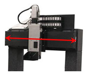
Air bearing stage specifications are typically quoted with the assumption that the stage will be mounted on a flat horizontal plane. If the mounting orientation is to be something else (vertically, as in a Z axis; or on the side, as in an overhead bridge), then the specifications will typically require larger error motions. Side mounting (see Figure 6) can be especially challenging for straightness. The gravity load on the stage base and the bridge beam induce sagging, and therefore straightness errors. Attempts can be made to compensate for this at machine build time, but the errors usually cannot be fully overcome.
5. Repeatability of straightness and flatness error motion
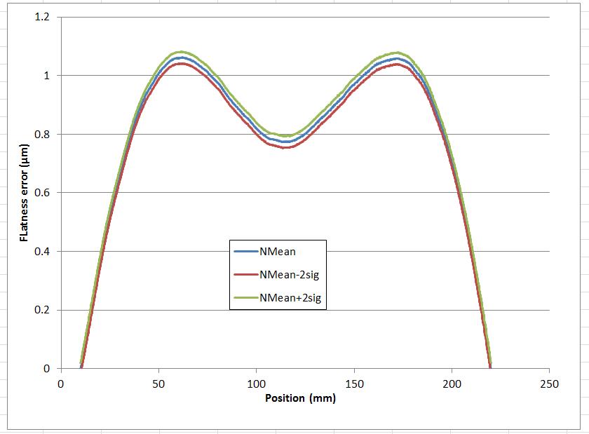
Air bearing stages can claim not only very low overall straightness and flatness error motions, but also extremely repeatable and stable errors as well. The data in Figure 7 shows the flatness error measurements taken from the same stage five successive times. The 2-sigma repeatability of the flatness error is less than 50 nanometers in this case. Since air bearings contain no wear items, one can assume this level of performance will not change over time, unless the machine installation and/or operating conditions are somehow changed.
6. Short-term error motion
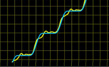
The most exceptional example of the extreme precision of air bearing stages can been seen when we examine the short-term effects of straightness and flatness error motions. In Figure 8, we see the straightness data for a stage taken over 10mm of travel. The TIR measurement in this case is less than 15 nanometers. Errors over any 1mm segment are less than 10 nanometers.


Blog Categories
- Aero-Space
- Air Bearing Stages, Components, Systems
- Astronomy
- Automation, Nano-Automation
- Beamline Instrumentation
- Bio-Medical
- Hexapods
- Imaging & Microscopy
- Laser Machining, Processing
- Linear Actuators
- Linear Motor, Positioning System
- Metrology
- Microscopy
- Motorized Precision Positioners
- Multi-Axis Motion
- Nanopositioning
- Photonics
- Piezo Actuators, Motors
- Piezo Mechanics
- Piezo Transducers / Sensors
- Precision Machining
- Semicon
- Software Tools
- UHV Positioning Stage
- Voice Coil Linear Actuator
- X-Ray Spectroscopy