1. Introduction
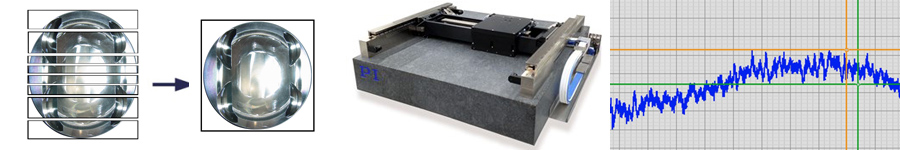
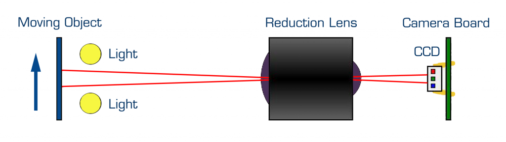
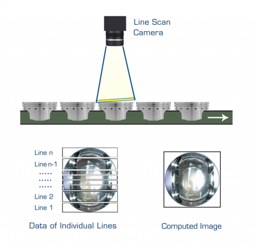
A common application in which an air bearing is specified is scanning. Scanning involves moving either a work-piece or an optic at a constant velocity, while a reading or writing operation takes place. Such operations include printing and image-setting (i.e., writing) and imaging (i.e., reading). While the physical act of writing an image or capturing an image differ by application and industry, all such applications share a common requirement – maintaining a constant velocity. In most applications, the image capture or creation operation takes place at a constant frequency (i.e., frames per second in a camera). As the optic and work-piece move relative to each other, the spatial separation between each frame must be constant in order not to distort or blur the image. This means that the relative velocity between the two must remain constant.
In this technical note, we will discuss several aspects of scanning performance: how it is specified and measured, what performance level is achievable, what can impact the performance, and why air bearings provide superior scanning performance.
2. Definitions: How To Define Scanning Performance
The two most common methods of defining and specifying scanning performance are based on either velocity or position.
A velocity-based specification is often defined as a percentage error at a specific velocity.Example: 200 mm/sec scan speed, 0.01% error.
A position-based specification is described in terms of position error at any point in time, also called following error. It means that the stage position cannot deviate from the planned motion trajectory by more than the error window during the entire scan. Example: 200 mm scan distance, 200 mm/sec scan speed, +\-0.1 micron following error.
Following error is a common term in the servo controls domain. It is a general term used to define the position error between the commanded trajectory vs. the actual trajectory. In this article, we use the term in this way, but in the specific case of errors seen during the constant velocity scan move. We ignore the following errors seen during a contoured move, where trajectory changes, and therefore accelerations, are commanded by the controller.
At PI, we prefer to use the position-based specification for scanning performance, as the errors are more directly measured using laser interferometry tools.
3. Why Air Bearings Provide Superior Scanning Performance
3.1 Bearings
Air bearings provide superior scanning performance when compared to traditional mechanical technologies for one main reason: air bearings have no friction. An air bearing has no physical contact between moving parts and floats on a cushion of air. Thus, air bearings do not need to overcome static friction in order to produce motion and do not need to overcome dynamic friction to maintain motion. With the minor exception of drag forces created by aerodynamic drag from the surrounding atmosphere and viscous drag created by the shearing of the air bearing film, an air bearing system behaves exactly as Newton’s three laws of motion predict. In fact, air bearings are often used in physics classrooms to demonstrate ideal Newtonian motion.
Mechanical bearings suffer from two weaknesses that impact scanning performance: friction and noise. All mechanical bearings exhibit some level of static and dynamic friction that must be overcome by the drive and control system. Friction levels can change with temperature, lubrication, preload, speed, payload, and wear. This makes friction behave in unpredictable and non-linear ways. Further, the friction levels can vary widely from unit to unit. Mechanical bearings, especially those with reciprocal elements, also suffer from noise. As rolling elements (balls or rollers) exit the bearing groove, recirculate in their carrier, and then re-enter the bearing groove, audible noise can be heard. This noise varies with speed, and the noise heard by the ear affects the motion profile. Both friction and noise make it impossible for the servo controls to maintain ideal scanning performance.
3.2 Drive System – Frictionless Motors
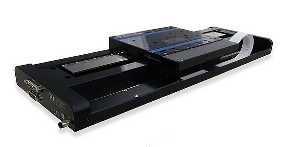
Any PI air bearing stage designed for scanning is driven by a direct-drive linear motor. Linear motors, like air bearings, have no contacting moving parts, and therefore do not suffer from noise and friction issues. Traditional mechanical drive mechanisms, such as screws, worms, belts, and gears, all suffer from the same weaknesses as mechanical bearings: friction and noise. By coupling non-contact air bearings with non-contact linear motors, PIglide air bearing stages create friction-free motion perfect for scanning.
4. Other Impacts On Scanning Performance
Not all air bearing motion systems are created equal. Yes, the use of an air bearing and linear motor are necessary to scanning, but other design decisions will impact system performance as well. These factors must be considered and tradeoffs made during system design. PI engineers will consider your specific application to determine how to best meet your scanning performance specifications.
Some aspects to consider include:
- Payload
- System stiffness
- Motor design
- Encoder selection, resolution, and signal type
- Servo controls and drives selection
- Cable track design
- Electrical noise isolation and wiring design
- Vibration isolation and control
5. Scanning Performance Levels
The level of achievable scanning performance will vary from system to system. However, we include here some performance data captured from some PIglide air bearing stages to give the reader a sense of what can be achieved.
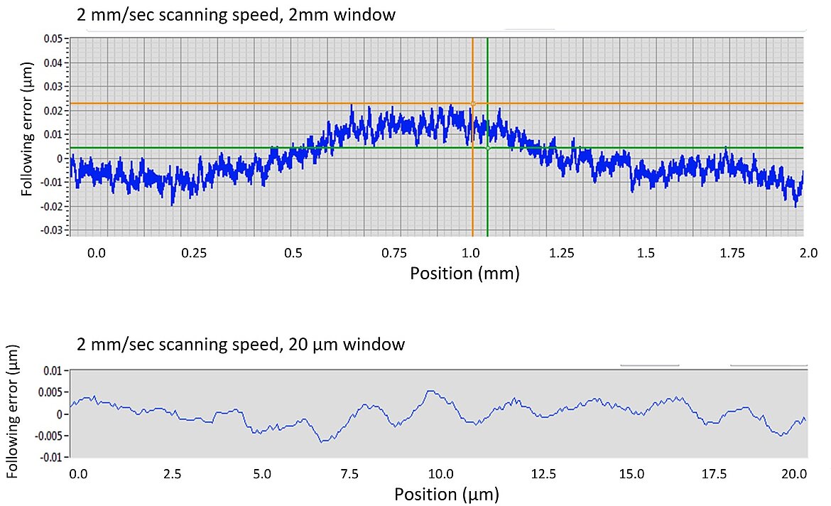
This set of data is taken from a model A-110 PIglide LC linear air bearing stage with a 2µm incremental optical sine/cosine analog encoder with a glass scale. This encoder was chosen for its extremely good signal-to-noise quality. The stage is operated with an ACS SPiiPlus EC motion controller. Following errors are below +\-20 nanometers at a scan speed of 2 mm/sec. Over a small window of 20µm of travel, the following error is below +\-10 nanometers.
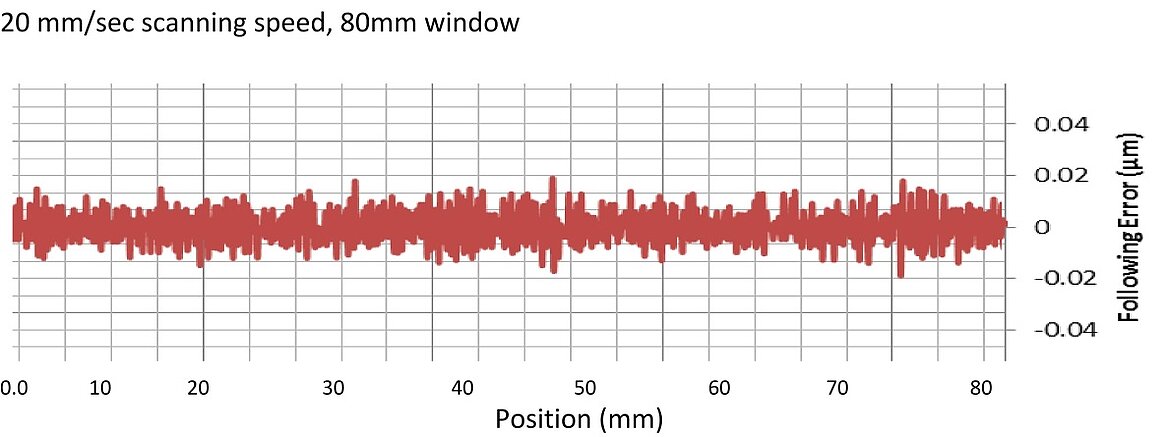
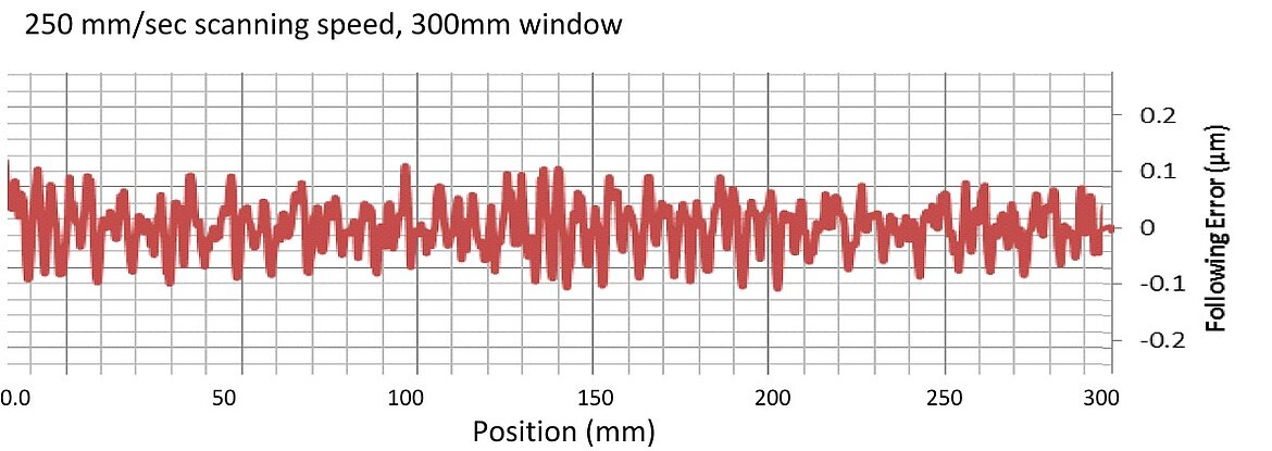
This set of data is taken from a model A-322 PIglide HS planar XY air bearing stage with absolute optical encoder, 1nm BISS output, and steel scale. The stage is operated with an ACS SPiiPlus EC motion controller. Following errors are below +\-25 nanometers at a scan speed of 20 mm/sec, and below +\-100 nanometers at a scan speed of 250 mm/sec.


Blog Categories
- Aero-Space
- Air Bearing Stages, Components, Systems
- Astronomy
- Automation, Nano-Automation
- Beamline Instrumentation
- Bio-Medical
- Hexapods
- Imaging & Microscopy
- Laser Machining, Processing
- Linear Actuators
- Linear Motor, Positioning System
- Metrology
- Microscopy
- Motorized Precision Positioners
- Multi-Axis Motion
- Nanopositioning
- Photonics
- Piezo Actuators, Motors
- Piezo Mechanics
- Piezo Transducers / Sensors
- Precision Machining
- Semicon
- Software Tools
- UHV Positioning Stage
- Voice Coil Linear Actuator
- X-Ray Spectroscopy