
PILine® positioning systems are based on a direct drive using ultrasonic piezo motors. Therefore, very low response times as well as accurate positioning can be accomplished. Due to the particular operating principle, PILine® ultrasonic motors are self-locking even when switched off, a great advantage when it comes to position stability. Ultrasonic motors are not frictionless like voice coils or linear motors, which are better suited for continuous high speed scanning. Nevertheless, PIline® ultrasonic motors have achieved a very high level of durability.
This white paper is intended to provide a better understanding of what this wear is and what it means in terms of product lifetime. Furthermore, it focuses on showing why and under which circumstances neither lifetime nor general reliability is an issue when using PILine® motors.
2. Operating Principle of PILine® Positioning Systems
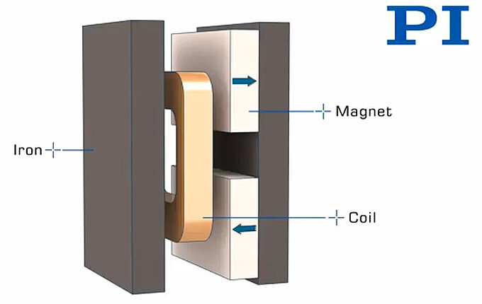
The actuator is excited electrically to generate highfrequency oscillations. In conjunction with preloading, continuous fast- feed motion results. The oscillation of the piezoelectric actuator is based on crystalline effects and is therefore completely free of wear.
At the core of every PILine® system, a piezoelectric actuator is preloaded against a runner using a coupling element (see Fig. 1).
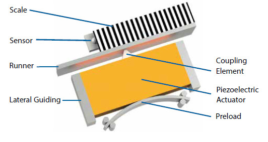
The contact between the coupling element and the runner on the other hand, is subject to friction. Since this contact can account for up to 40 % of the system’s total energy loss, great effort is made to determine the optimum composition of materials used.
Runners and coupling elements made of alumina (Al2O3) or zirconia-toughened alumina (Al2O3/ZrO2, ZTA) have proven to be most effective.
3. Implications of Wear
Due to the friction-related power transfer between the coupling element and the runner, abraded particles accumulate in the housing of the motor (see Fig. 2).
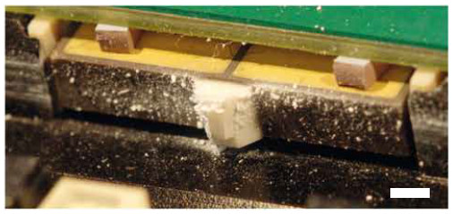
However, the use of ceramic coupling elements keeps the degree of abrasion to a minimum. Furthermore, the coupling elements are dimensioned to prevent critical abrasion levels from being reached within the specified lifetime. Due to electrostatic effects, a large quantity of abraded particles remains in the housing because they are attracted directly to the piezoelectric actuator and coupling element.
3.1 Wear over Time
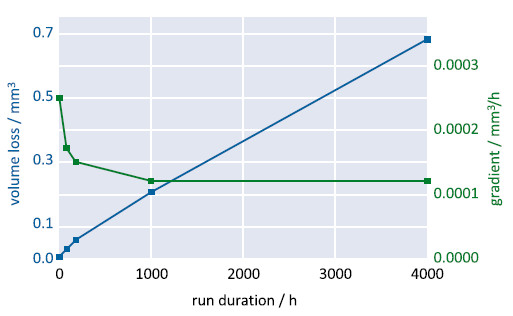
During the run-in period (approximately 100 h), unevenness caused by minor imperfections in the alignment between the coupling element and the runner are smoothed. After this initial process, the volume loss decreases to a low, constant value as visualized exemplarily in Fig. 3.
3.2 Surfaces
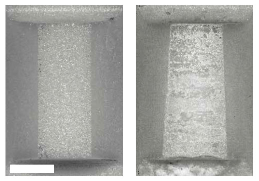
On delivery, the surfaces of the ceramic coupling element and runner are smoothly polished. During the run-in procedure, asymmetry of the alignment is compensated by material abrasion. Over the course of a lifetime, signs of wear as well as effects of asymmetric alignment are visible on the surfaces of the coupling element and the runner.
The outcome of a 19,000 h lifecycle test of a PILine® M-663.5U linear stage test is discussed below, where these impacts can be readily observed. For more details on the test, refer to chapter 4.2. Wear and degree of abrasion on the coupling element and the runner are analyzed in Fig. 4 and Fig. 5, respectively. During the lifecycle test, the average height of the coupling element decreased by about 60 μm, with more than 85 % of the original height (400 μm) remaining. The removed volume amounts to approximately 0.05 mm³ (0.2 mg) of the abraded material.
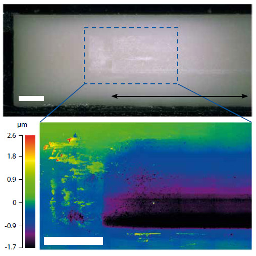
The mean abrasion depth of the runner was estimated to be approximately 1 μm in the contact area of the coupling element, as described in Fig. 5. From profile scans, an abrasion volume of 0.03 mm³ (0.11 mg) can be estimated.
In total, this particular PILine® linear stage has produced approximately 0.08 mm³ (0.31 mg) abrasion. Therefore, after an initial run-in period, an abrasion volume of less than 0.02 μg/h can be expected, assuming constant wear.
3.3 Grain Size and Composition of Abrasion
The grain size of the abraded material was determined to be below 1 μm, as shown in Fig. 6.
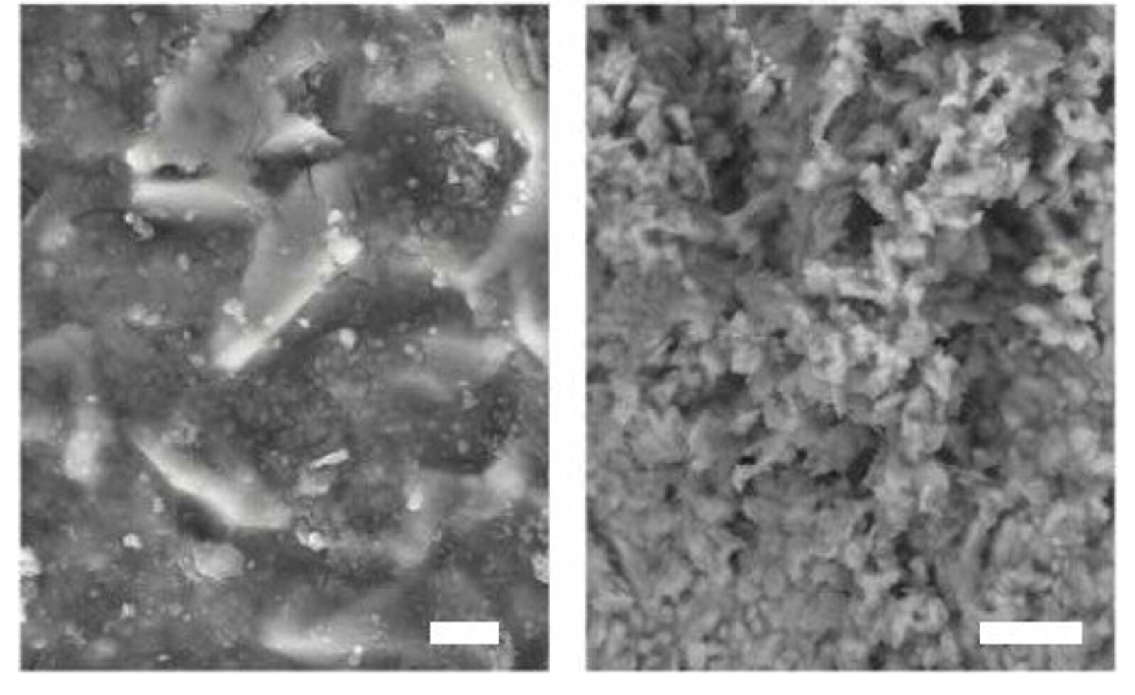
However, the appearance of single, isolated particles is rare; most particles agglomerate to large clusters.
The composition of the abraded particles was analyzed using electron diffraction x-ray (EDX). It corresponds to that of the ceramic coupling element and runner; therefore these can be identified as the sole source materials. As such, the abraded particles are electrically nonconductive, chemically inert and should not pose any danger to your electronic components. Furthermore, they have no impact on the performance of the PILine® motors.
4. Case Studies
During product development, numerous tests are conducted which are designed to meet customer requirements as well as attain the anticipated lifetime. The following representative case studies highlight some of our products.
4.1 Total Stations – Leica Geosystems
Leica Geosystems, a leading manufacturer of high-precision surveying instruments, relies on PILine® direct drive technology in their new total station product line (see Fig. 7).
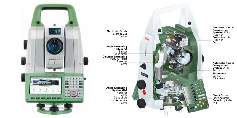
Total stations are used for angle and distance measurement in geodesy. Customer requirements included an extensive increase of the rotation speed and the angular resolution compared to the previously used conventional drive. To verify the fulfillment of these requirements, a test recreating the typical usage of the device was conducted. It consisted of rotating a mass of 6 kg (15,000 kg/m²) in alternating directions. After completion of the test with a total of 7,000 h or 2,500 km of operation, all customer specifications continued to be fulfilled. The corresponding test with the analysis of the wear on the motor is shown in Fig. 3.
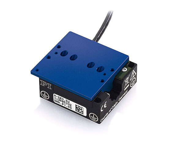
4.2 PILine® M-663.5U Translation Stage
The PILine® M-663.5U is a very fast and versatile linear translation stage. Due to its versatility, customers are expec- ted to use it in unconventional situations or, more specific, suboptimal mounting orientations.
However, the mounting orientation has a significant impact on product wear due to the varying load on the coupling element and bearings. Fulfillment of the requirements on product lifetime was validated during a long-term test, where the stage was mounted at the least-favorable mounting orientation as depicted in Fig. 8.
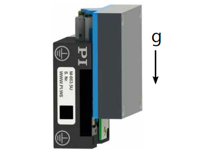
During this test, the stage travelled continuously across the full available travel range of 18 mm at a speed of 20 mm/s. A maximum applicable load of 2 N was determined as one of the test results. All stages remained in good condition during the trial period of over 19,000 h or 600 km, fulfilling the specifications as stated in the data sheet. Further analysis of the coupling elements and runners in these stages is discussed in chapters 3.2 and 3.3.
4.3 Customized PILine® M-663 Stage
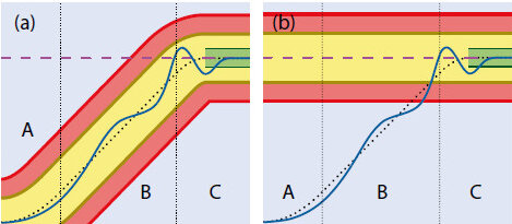
This case study deals with a specifically customized PILine® M-663 stage. The customer requested a maximum permissible target deviation of ±1.2 μm and a settling time less than 250 ms. Both requirements were verified in longterm tests as presented in Fig. 9.
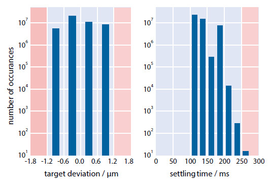
After performing 45.6 million positioning cycles (380 km), the stage only failed to reach the target 15 times within the requested settling time, which is equivalent to 0.33 failures per million. The target deviation always remained below the threshold of ±1.2 μm.
5. Factors Influencing Wear
Depending on the ambient conditions, under which PILine® motors are operated, impact on wear may vary (see Tab. 1). This chapter intends to give you advice on how to maximize the lifetime of your PILine® positioning systems.
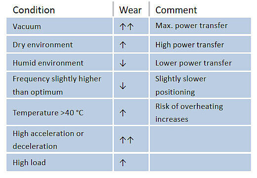
5.1 Humidity
The degree of abrasion depends on the power transmitted via the coupling element, which in turn depends on environmental conditions. Dry environments enable higher power transmission at the cost of increased wear. This is especially true under vacuum conditions, where maximum power transmission can be achieved. However, in humid environments, power transmission between the coupling element and the runner is reduced due to lower friction.
5.2 Temperature
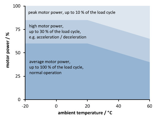
The ideal operating temperature for PILine® motors is between 10 °C to 40 °C. At lower temperatures, power transmission and maximum achievable speed are reduced due to the decreased inverse piezoelectric effect. For operation at temperatures above 40 °C, a reduction of motor power is advised to prevent overheating (see Fig. 10).
5.3 Load
Extended operation at high motor power leads to overheating and causes wear that could be prevented.
- It is recommended to keep the motor output below 60 %. The remaining 40 % is dedicated to acceleration, deceleration and use as a control reserve.
- PILine® motors undergo the heaviest load during acceleration and deceleration, while overcoming stiction. Try keeping them as low as possible, especially when moving heavy masses. Generally, 1,000 mm/s² is a good value, although a PILine® motor can easily achieve 10,000 mm/s².
- When targeting the same destinations repetitively, bumps may form on the runner. From time-to-time, try targeting a destination further away to promote smoothening of the runner surface.
6. Conclusion
Despite the wear-related drive principle, PILine® piezo motors are perfectly fit for applications where continuous operation is required.
As a general rule of thumb, PILine® systems typically reach 2,000 h of operation, 2,000 km or 20 million cycles, whichever occurs first.
Author: Dr. Christian Benz is development engineer for piezomotor products at Physik Instrumente (PI) GmbH & Co. KG.


Blog Categories
- Aero-Space
- Air Bearing Stages, Components, Systems
- Astronomy
- Automation, Nano-Automation
- Beamline Instrumentation
- Bio-Medical
- Hexapods
- Imaging & Microscopy
- Laser Machining, Processing
- Linear Actuators
- Linear Motor, Positioning System
- Metrology
- Microscopy
- Motorized Precision Positioners
- Multi-Axis Motion
- Nanopositioning
- Photonics
- Piezo Actuators, Motors
- Piezo Mechanics
- Piezo Transducers / Sensors
- Precision Machining
- Semicon
- Software Tools
- UHV Positioning Stage
- Voice Coil Linear Actuator
- X-Ray Spectroscopy