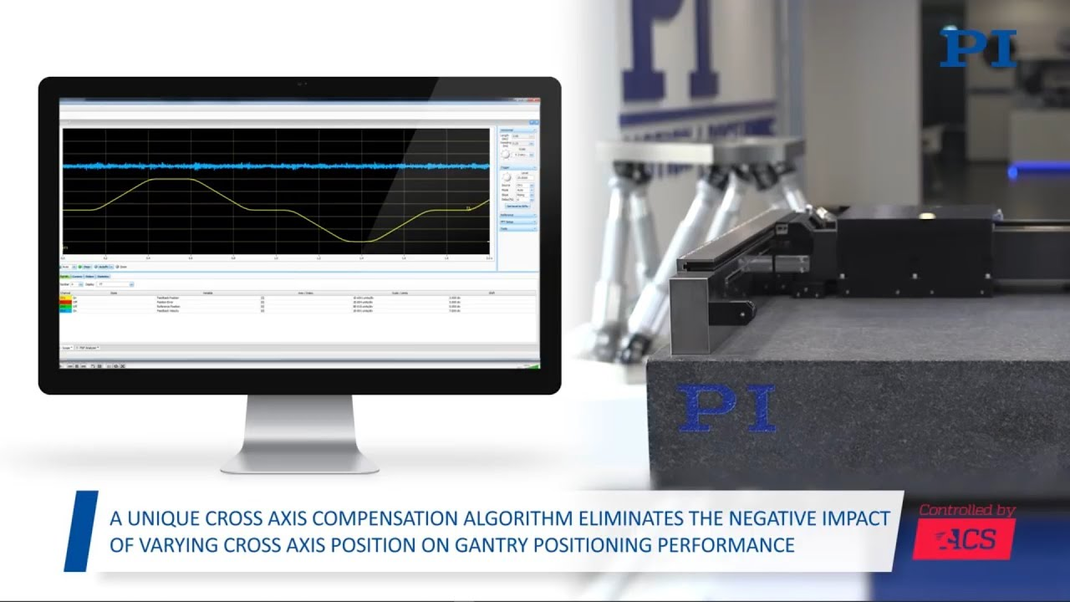
Precision motion systems always exhibit some amount of positioning inaccuracy (or position error) due to various factors. These errors can be measured using external measurement devices, such as a laser interferometer, and can then be corrected by changing the motion profile according to an error correction map. The ability to change the motion profile according to a preset correction map is called Dynamic Error Compensation and is a standard feature in all ACS SPiiPlus controllers used by PI.
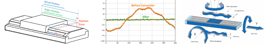
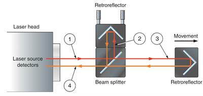
Position accuracy (also called positioning error) is defined as the difference between the ideal target position to which the system was commanded to move (in the direction of travel) and the actual position as measured by an external metrology device, typically a laser interferometer.
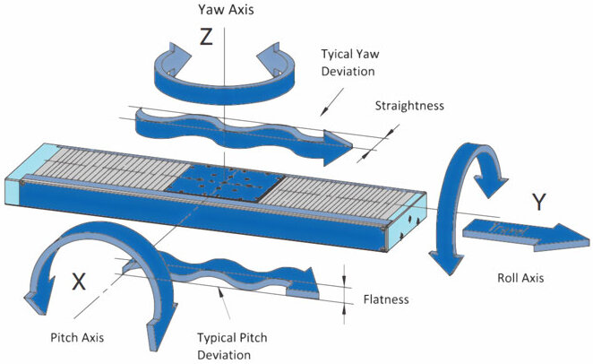
Position accuracy is influenced by imperfections in the position feedback system (such as a linear encoder), drive mechanism, guidance errors of the bearings, and deflection of the structure to which the stage is mounted. For more information, read also Straightness and Flatness of Air Bearings.
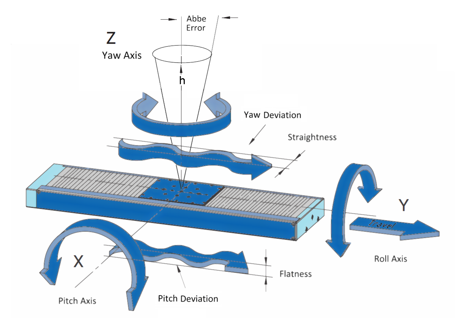
Position accuracy is also influenced by the location in space relative to the stage where the user’s payload or sensor is located. This location is called the “point of interest”, and the distance between this point and the stage is called an offset. Abbe error is the positioning error resulting from angular error motion of a stage’s moving part and the size of the offset. The greater the offset distance between the stage and the user’s point of interest, the greater the Abbe error. In the diagram shown below, the amount of pitch error from the stage combined with the length of the Abbe offset “h” will determine the Abbe error.
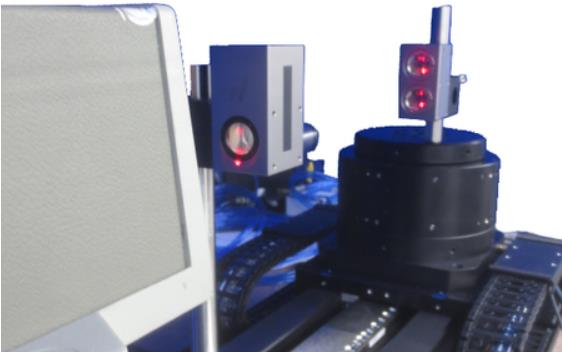
This test is performed with a retroreflector mounted to the stage’s moving table, with the optic located at the user’s point of interest. By doing this, the Abbe error is captured in the measurement.
The interferometer beam splitter optic is placed at the end of the stage and is held stationary. The beam path is in the direction of motion.
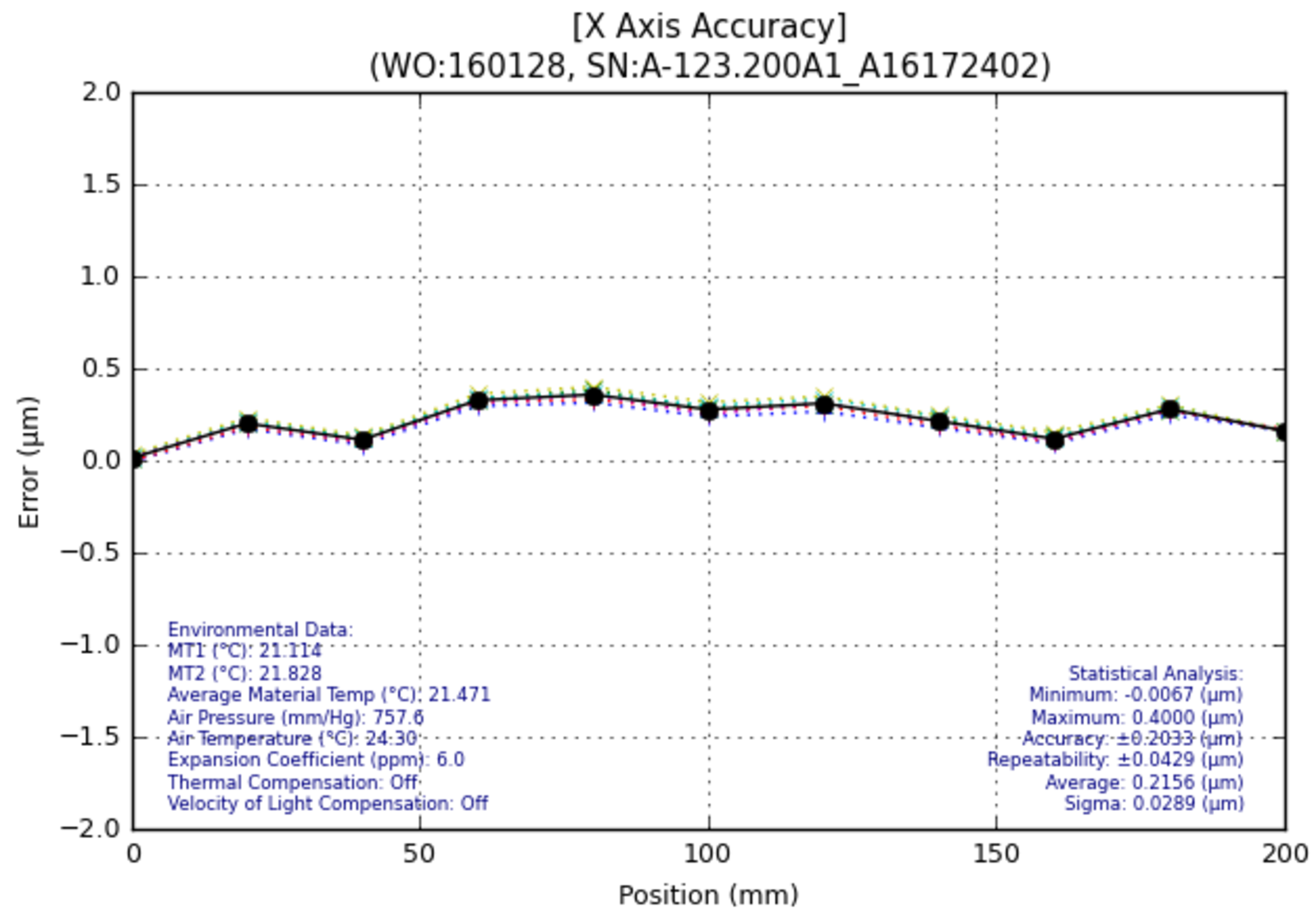
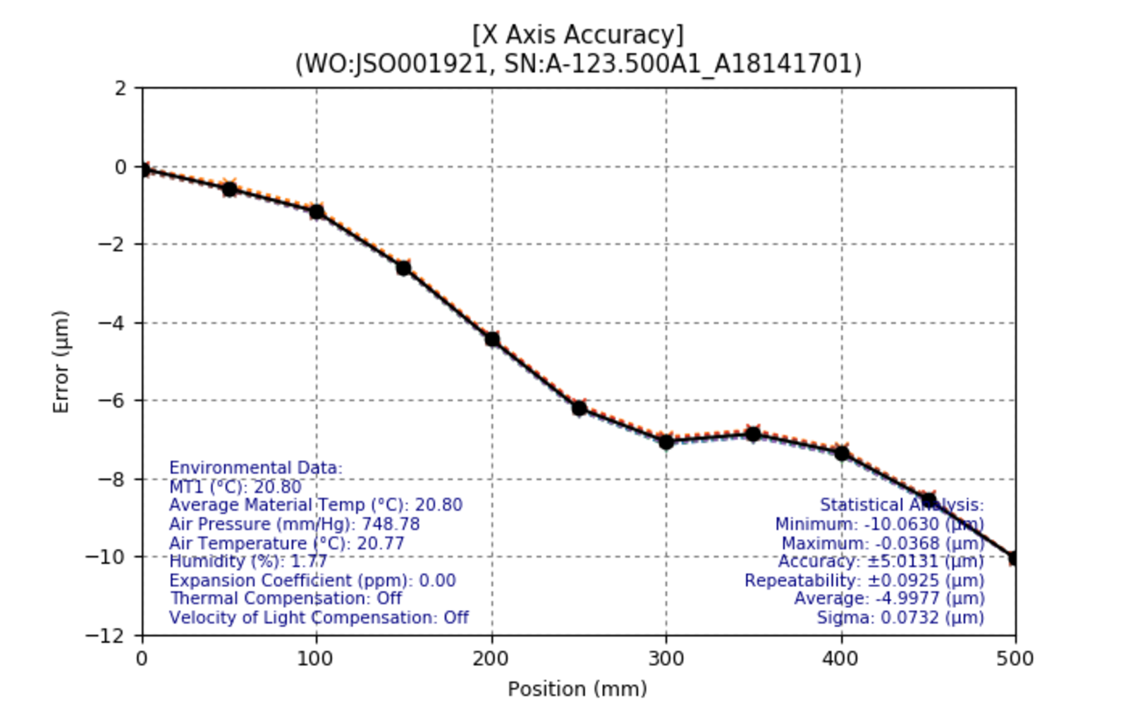
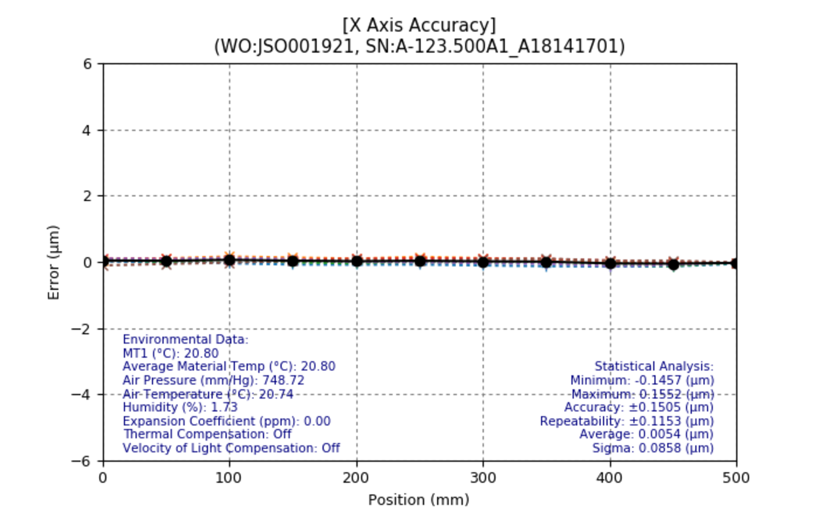
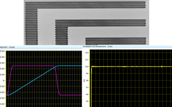
Under closed loop servo control, the stage is moved in fixed increments (typically 10mm – 50mm per step), and a measurement is taken at each point. The stage is moved through its full length of travel in both directions for multiple passes. The collected data is plotted and the overall accuracy is calculated. The accuracy and repeatability results are typically reported in microns.
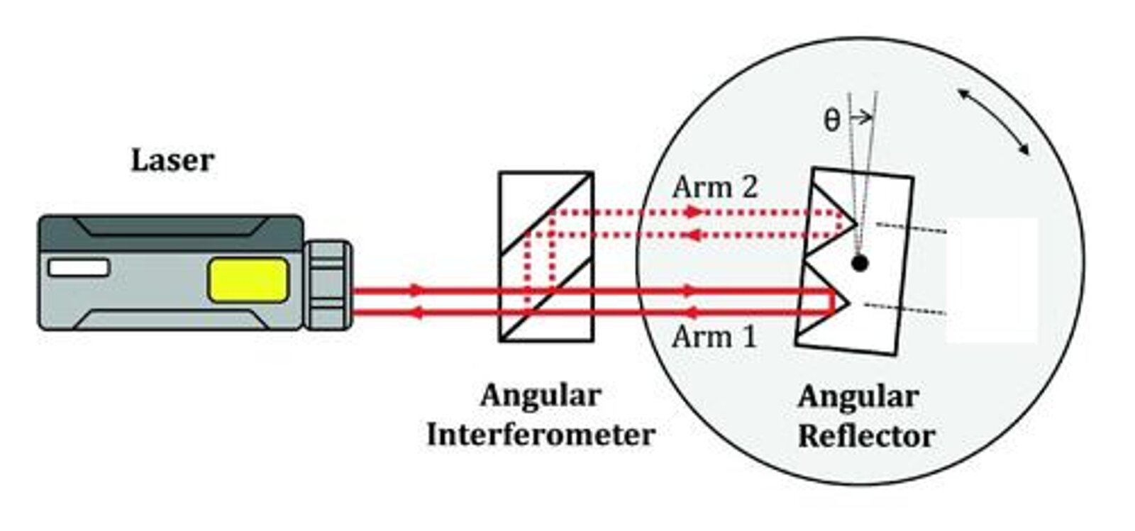
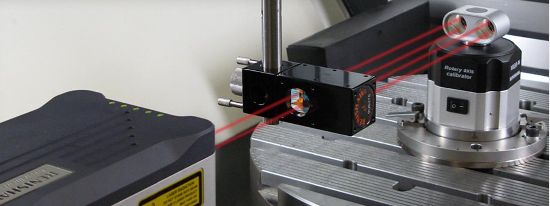
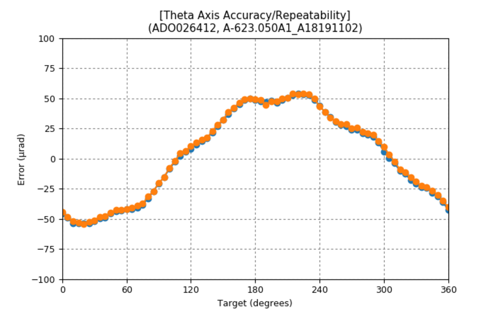
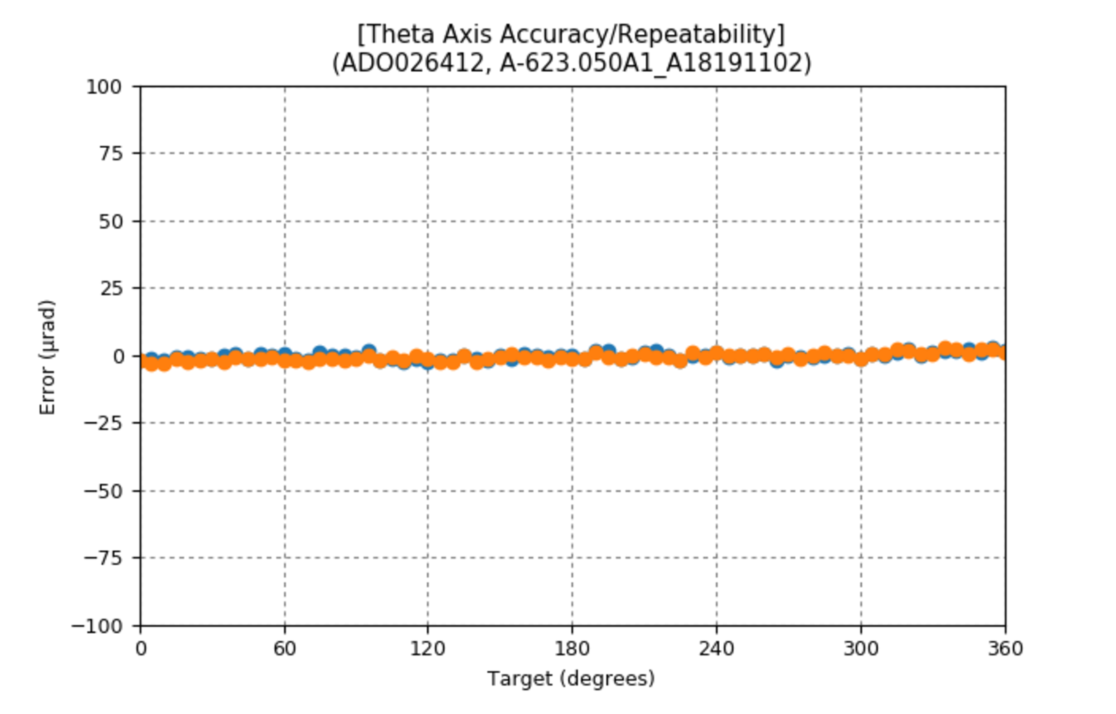
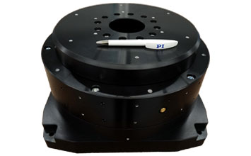
This test is performed using the Renishaw XR20-W rotary axis calibrator mounted to the rotating stage table. The XR20-W consists of an integrated angular retroreflector mounted on a precision servo-controlled axis. The angular position of this axis, and the optics relative to the main body housing, is controlled by a very high accuracy encoder system with the scale directly machined onto the main bearing. The angular interferometer optic is placed at the end of the stage and is held stationary. The angular optic setup creates two beam paths. As the stage rotates, the XR20-W counter-rotates by the same amount. The angular error is calculated based residual rotation measures by the laser.
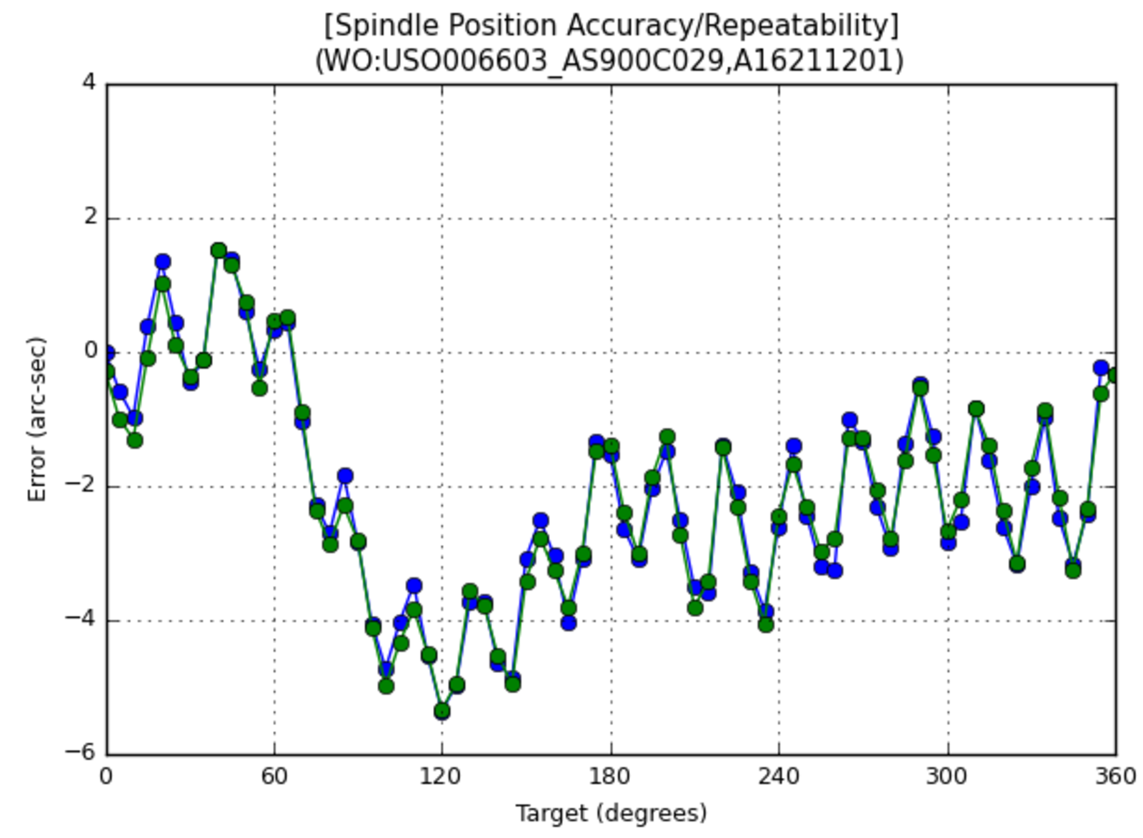
In the same way that the linear accuracy data is collected, the stage is moved in fixed increments (typically 5° - 30° per step), and a measurement is taken at each point. The stage is moved through its full range of travel, in both directions, for multiple passes. The data that is collected is plotted and the overall errors are calculated. The results are typically reported in arc-seconds or microradians.
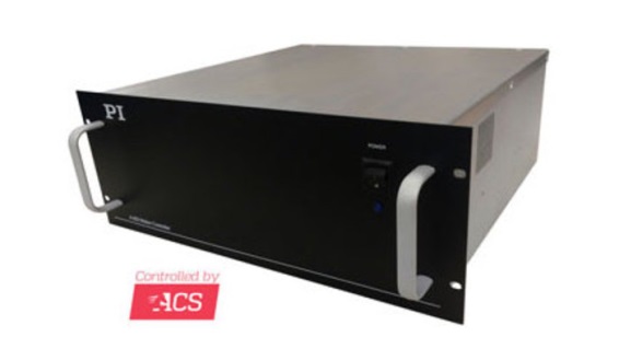
Using data from the position error measurements, a correction table can be generated and loaded into the ACS motion controller. The errors are corrected by changing the motion profile on the fly, according to the correction map, via a controller feature called Dynamic Error Compensation.
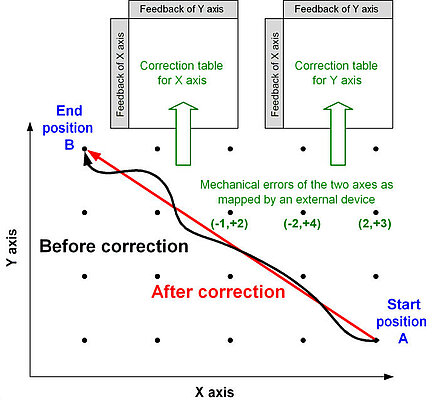
Dynamic Error Compensation constantly provides a corrected trajectory to the stage. This means the error corrections are made while the stage is in motion, not just at the end of a move. True position tracking during motion is achieved in this way. The controller also interpolates between the discreet points provided in the correction table.
Shown below are typical position error plots for PIglide air bearing stages taken before and after the implementation of Dynamic Error Compensation using an ACS SPiiPlus Motion Controller. The final results that can be obtained with error compensation are limited only by the repeatability performance of the stage.


Blog Categories
- Aero-Space
- Air Bearing Stages, Components, Systems
- Astronomy
- Automation, Nano-Automation
- Beamline Instrumentation
- Bio-Medical
- Hexapods
- Imaging & Microscopy
- Laser Machining, Processing
- Linear Actuators
- Linear Motor, Positioning System
- Metrology
- Microscopy
- Motorized Precision Positioners
- Multi-Axis Motion
- Nanopositioning
- Photonics
- Piezo Actuators, Motors
- Piezo Mechanics
- Piezo Transducers / Sensors
- Precision Machining
- Semicon
- Software Tools
- UHV Positioning Stage
- Voice Coil Linear Actuator
- X-Ray Spectroscopy