- OEM / SystemsOEM Systems | Precision Components | Automation Sub-SystemsPI offers 1000’s of proven, off-the-shelf precision motion products that can be quickly modified for the OEM or into a custom automation sub-system.
- Meeting the Demands of OEMsOEM Systems | Precision Components | Automation Sub-SystemsPI has a long track record of working with OEMs in the most demanding industries from Semiconductor Technology to Medical Design – industries where product performance, quality, and the ability to ramp up quickly are not the only parameters required to satisfy the customer's demands. Working with technology leaders all around the world forces you to continuously improve your yield, process, and product performance. And unless your quality is outstanding, you cannot become a key supplier to major US, European, and Japanese companies in the Optics, Photonics, Semiconductor, and Automotive industry.
- Engineered Motion / Automation Sub-SystemsPrecision Automation Solutions | Engineered SystemsPI is a supplier of high-end precision motion systems and makes use of own drive components and high-precision positioners to build customized positioning and automation sub-systems —“motion engines”—for our customers. With the largest portfolio of precision motion technologies in the industry, PI engineers have the best foundation to find a solution that matches your requirements in terms of precision, quality and budget – in a timeframe that works for you.
- Meeting the Demands of OEMs
- ProductsPrecision Motion Technologies | Positioning SystemsOverview of the Broadest & Deepest Portfolio of Precision Motion and Automation Technologies from Piezo to Air Bearings and Linear Motors
- Products: Overview, New, Finder, ShopFind Precision Positioning Solutions Quickly - Product Finder | PI USAWith thousands of standard products and customization available, PI has the motion control positioning product solution for your application.
- Products OverviewProducts OverviewOverview of the Broadest & Deepest Portfolio of Precision Motion and Automation Technologies from Piezo to Air Bearings and Linear Motors
- New ProductsNew Motion Control & Precision Positioning Products | PI USALearn about the latest innovations in motion control and nanopositioning components and systems.
- Product FinderUse the PI Product Finder - it's fast and easy!Select the product type specified by the axes of motion required. Selection of more criteria expands or shortens the list of results. Select more than one filter at at time, for example, to find positioning stages designed for higher load capacity, too.
- ► Shop► ShopShop for select PI products online
- Products Overview
- Air Bearings & Ultra High Precision StagesAir Bearing Stages | Motorized | Linear | RotaryAir bearings provide advantages over mechanical bearings when vibration-free motion is required, highly constant velocity control is crucial, and when angular repeatability and geometric performance must be optimal. Air bearing stages (linear, rotary, and spherical) replace mechanical contact by a thin air film, avoiding wear, friction, vibration, and hysteresis effects.
- Miniature Positioning StagesMiniature Positioning Stages | Supplier | ManufacturerCompact positioning stages are crucial for the miniaturization process in cutting-edge research and industrial applications, for test & measurement, optical and opto-mechanical alignment, and component assembly. PI provides the largest portfolio of miniature stages, including high-speed linear motor stages, economical stepper motor units, and ultra-compact piezo motor positioners.
- Motorized Stages: Linear, Rotary, XYMotorized Stages | Positioning | ManufacturerPI offers the broadest and deepest range of precision motion technologies for micro and nano precision applications. Our engineers work with our customers to find the best drive and bearing technology for each individual application. Having access to multiple drive and positioning technologies allows an open discussion with a better outcome for the customer.
- Overview - Motorized Linear/Rotary StagesOverview - Motorized Linear/Rotary Stages
- Linear StagesLinear Stages - Precision Positioning Solutions | PI USASeveral types of motorized precision linear translation stages | PI USA
- Fast Linear Motor Stages and ActuatorsOverview: Linear Stage, Linear Motor Driven, Fast Brushless Motor Positioning Stages | PI USABrushless linear motor-driven stages provide high speed, precision and long life.
- Z-Stages (Vertical Motion)Vertical Linear Stages – Precision Motorized Z-Positioners | PI USA
- XY StagesXY Stages – 2-Axis Motorized Precision Positioning Stages | PI USASeveral types of planar XY stages: Direct-driven stages, ball-screw stages and air bearing planar XY stages
- XYZ StagesXYZ Stage - Multi-Axis Precision Motorized Stages
- Rotary Stages / GoniometersPrecision Rotation Stage, High Resolution Rotary Positioners, Rotation Tables, Goniometers, by PI USASeveral types of motorized rotation stages: Direct-driven stages, ball-bearing stages and air bearing stages
- Heavy Duty Stages / Industrial AutomationHigh Speed / Performance Positioning Stages for Automation - Linear Stages | Rotary Stages | PI USAHigh performance motorized stages, designed for heavy duty applications in industrial precison automation.
- Sub-Systems for AutomationSYS > Engineered Motion/Automation Sub-SystemsThe PI group employs over 1,200 people in 15 countries and runs engineering and manufacturing centers on 3 continents. Select from the broadest portfolio of precision motion technologies, including piezoelectric and air bearing systems, with 1,000’s of standard products or have our engineers provide you with a custom solution.
- Overview - Motorized Linear/Rotary Stages
- Linear ActuatorsActuators | Precision | Linear | Actuator SystemA precision linear actuator is a positioning device that provides motion in 1 degree of freedom. PI designs and manufactures a variety of precision linear actuators (pushers) including economical stepper-motor driven actuators, high-speed linear motor types for automation and nanometer precise piezo-motor actuators.
- Gantries / Cartesian RobotsGantry Stages | Gantries | Cartesian RobotA gantry precision positioning stage is sometimes called a linear robot or Cartesian robot. Gantries typically provide motion in 2 or 3 linear degrees of freedom (X-Y and X-Y-Z) and are often used for pick and place applications, 3D printing or laser machining, and welding applications.
- 6-Axis Hexapods / Parallel PositionersHexapod Positioner | Six DOF | Stewart PlatformsHexapod positioners are often referred to as Stewart Platforms. A hexapod is based on a 6-axis (XYZ, Pitch, Roll, Yaw) actuator system arranged in parallel between a top and bottom platform. PI parallel kinematics (PKM) precision positioning systems have many advantages over serial kinematics stages, such as lower inertia, improved dynamics, smaller package size and higher stiffness. In addition hexapods are more flexible than conventional 6 axis positioners.
- 6-Axis Hexapods / Parallel Positioners6-Axis Hexapods / Parallel Positioners
- Control of Hexapod / Stewart Platforms: Hexapod Motion Controllers & Simulation Software6DOF Motion Platforms | Hexapod Controllers & Simulation Software | Stewart Platform | ManufacturerControllers, software and accessories for Hexapod Stewart platforms and parallel kinematic motion systems | PI USA
- 6-Axis Hexapods / Parallel Positioners
- Piezo Flexure Nanopositioning StagesNanometer Precision: Piezo Stages for Nanopositioning, Piezo Nanopositioners, Piezo Flexure Scanning Stages | PI USAPI offers the broadest and deepest portfolio of nanometer precision motion technologies, from piezo-driven nanopositioning and scanning stages to motorized 6-axis hexapod positioning systems.
- Overview - Piezo Flexure StagesOverview - Piezo Flexure Stages
- Linear Piezo Flexure StagesLinear Piezo Stages for Nanopositioning – Flexure-Guided Precision NanoPositioners | PI USALargest selection of frictionless, high performance piezo-stack-driven flexure linear nanopositioning stages | PI USA
- Vertical & Tip/Tilt Piezo StagesPiezo Z-Stage, Piezo Z-Tip-Tilt Platform. Flexure Guided Nanopositioning Stages| PI USALarge selection of Piezo Z-Stages and Tip/Tilt scanners with nanometer precision | PI USA
- Fast Steering Mirrors & Tip/Tilt PlatformsPiezo Steering Mirrors | Active Optics
- Nanofocus Lens ScannersFast Piezo Focus Lens Positioners and Scanners – Piezo Flexure Guided Precision Positioners | PI USALargest Selection of Nano-Focus drives for microscope lenses – flexure-guided precision positioners
- XY Piezo Flexure StagesPiezo Stages | XY | Nanopositioning StagesLargest selection of integrated XY piezo flexure stages with nanometer precision.
- XYZ Piezo Flexure StagesXYZ Piezo Nanopositioning Stages – Flexure Guided 3-Axis Precision Positioners | PI USALargest selection of integrated XYZ piezo flexure stages with nanometer precision.
- 6-Axis Piezo Flexure Stages6-Axis Piezo Nanopositioning Stages – Flexure Guided Precision Positioners | PI USAPiezo-driven fast steering mirrors (FSM) achieve nanoradian resolution and high bandwidth.
- Tutorial - Piezo NanopositioningNanometer Precision: Nanopositioning Basics Tutorial. Piezo Nanopositioners, Scanning Stages, Flexure Guided Positioners | PI USAThere are several ways to achieve nanometer precision motion. The best positioning systems avoid friction all together, in both the drive system (motor) and in the guiding system (bearings). Frictionless bearings also avoid the bearing rumble caused by balls and rollers and provide vibration-free motion with highly constant velocity.
- Overview - Piezo Flexure Stages
- Piezo Motors: Stages & ActuatorsPiezo Motors | Linear Motor Positioners | ManufacturerPiezo Motors are intrinsically vacuum compatible, non-magnetic and self locking at rest, providing long travel compared to traditional piezo mechanisms. The individual drive concepts are optimized for different applications, they differ in their design, size, cost, force & speed and other performance parameters.
- Overview - Piezo Motors (Stages/Actuators)Overview - Piezo Motors (Stages/Actuators)
- Actuators with Piezo MotorsCompact precision linear actuators stages with several types of piezo motor drives – ultrasonic, stick-slip, piezo-walk, piezo-ratchet. | PI USA
- Linear Stages with Piezo MotorsPrecision linear stages with several types of piezo motor drives – ultrasonic, stick-slip, piezo-walk, piezo-ratchet. | PI USA
- XY Stages with Piezo MotorsXY piezo motor linear stages with several types of precision piezo motor drives – ultrasonic, stick-slip, piezo-walk | PI USA
- XY Piezo Flexure StagesXY Piezo Flexure StagesHigh-precision 2-axis nanopositioning systems integrate PICMA® piezo actuators for maximum reliability. Repeatable, drift-free positioning with optimal stability is possible by the use of high-quality nanometrology sensors.
- Rotary Stages with Piezo MotorsRotary piezo motor stages with several types of precision piezo motors– ultrasonic, stick-slip (inertia), | PI USA
- Tutorial - Piezo Motion ControlWhy All Piezo Motors are NOT Created Equal: The piezoelectric effect for precision motion control - PI Physik Instrumente.The demand for higher speed and/or precision in fields such as bio-nanotechnology, semiconductors, metrology, data comm, and photonics keep pushing manufacturers to come up with innovative drive technologies.
- Overview - Piezo Motors (Stages/Actuators)
- Piezo Transducers & ActuatorsPiezo Actuator | Piezo Transducer | ManufacturerPiezoelectric translators (transducers) are precision ceramic actuators which convert electrical energy directly into linear motion with high speed, force and virtually unlimited resolution. These actuators are used in every modern high tech field from semiconductor test & inspection to super-resolution microscopy, bio-nanotechnology and astronomy/aerospace technology.
- Piezo Actuators & Transducers: Stacks, Chips, Benders, Tubes, Spheres, Shear…Piezo Actuators & Transducers: Stacks, Chips, Benders, Tubes, Spheres, Shear…
- Value-Added Piezo Transducers & Piezo AssembliesValue Added Piezo Assemblies: Transducers, Actuators, Sensors, Manufactured by PI CeramicDeveloping and manufacturing piezo ceramic materials and components are complex processes. PI Ceramic - PI’s piezo material design and manufacturing facility - boasts several decades of experience as well as the right tools for rapid prototyping of custom engineered piezo components and assemblies. From the formulation of advanced piezo materials to the processing steps such as cutting, milling, grinding, and the precision assembly, every stage is controlled by our engineers and product specialists.
- Piezo Ceramic ComponentsPiezo Ceramic Components
- Piezo Actuators & Transducers: Stacks, Chips, Benders, Tubes, Spheres, Shear…
- Microscopy, Bio-Imaging, Life SciencesHigh Precision Microscope Stages, Piezo Lens Scanners, Tools for Bio-Imaging | PI-USAPiezo nano-positioning stages are essential tools for high-resolution microscopy, such as Super Resolution Microscopy or AFM. Their sub-atomic resolution and extremely fast response allow researchers to create higher-quality images faster. PI provides a large variety of fast Z-Stages and collar piezo objective positioners for 3D imaging (Z-stack acquisition), deconvolution, and fast focusing applications.
- Stages for Microscopy & Bio-ImagingStages for Microscopy & Bio-Imaging
- Applications: Life Sciences / MedicalPrecision motion control for medical engineering and life sciences applications | PI USA
- Stages for Microscopy & Bio-Imaging
- Photonics Alignment SolutionsActive Photonics Alignment | Optics Alignment | SolutionsPI provides a variety of innovative fiber alignment systems from motorized fiber positioners to automated optic and photonic alignment such as used in telecommunication, data commumication and for packaging / automation. In addition to fiber-based applications, fast steering systems for free-space-optical communication are also available. Products range from motorized 6D micromotion alignment systems for industrial photonics automation, through ultra-fast piezoelectric scanning & alignment modules to modular devices with manual control for laboratory test setups. All motorized systems come with extensive software for easy setup and integration.
- Vacuum Positioning Stages & ActuatorsVacuum / UHV Compatible Stages - Linear & Rotary Positioners for Vacuum, Wide Temperature Ranges | PI USAPI miCos has extensive experience in the design and manufacturing of vacuum and high vacuum compatible precision optomechanical positioning equipment for low temperature and wide temperature ranges. We provide translation stages, vertical linear stages, rotation stages, XY stages and complex multi-axis positioning systems in vacuum spec.
- VacuumProduct Series with Vacuum-Ready ItemsPI offers specific catalogue items for selected product series that are already suitable for high vacuum (HV) or ultra-high vacuum (UHV).
- Vacuum
- Controllers, Drivers, Motion SoftwareMotion Controllers, Piezo Drivers-High Voltage Amplifiers, and Motion Software Overview | PI USA
- Overview - Controllers & Motion SoftwareOverview - Controllers & Motion Software
- Piezo Controller, Driver, Nanopositioning Controller, High-Voltage Amplifier, Piezo Power Supply by PI USAPiezo Drivers | Piezo Motion Controllers | ManufacturerA piezo controller or driver is used to control the motion of a piezo positioning device. There are open and closed loop controllers. Open-loop controllers are often referred to as piezo driver or even piezo power supply. Closed-loop controllers are divided in two basic types: analog-servo and digital servo controllers.
- Controllers/Drivers for Motorized StagesMotion Controller | Drivers | Positioning SystemsPI provides a large variety of hardware & software solutions for high precision motion control. Our portfolio spans from integrated compact single axis servo controllers / drivers, such as popular Mercury-class motion controllers, to complex multi-axis systems for parallel-kinematics positioners, such as hexapods.
- ACS Motion ControlACS Motion Control for Industrial AutomationWe recommend the controllers of our partner, ACS Motion Control especially for automation with industrial standards. Ask us about your integrated solution!
- Software - Motion Control SoftwareMotion Control Software | Software Tools | Positioning SolutionsFor LabView, C++, VB, Matlab, Image Acquisitiong Packages, NI DAC Cards, ..... PI provides high-level, robust, easy-to-use software tools for fast, seamless integration of motion systems into application control software.
- Overview - Controllers & Motion Software
- Capacitive SensorsNanometer Resolution: Capacitance Sensors for Nano-Measuring, Nano-Metrology | PIA capacitive sensor is a proximity sensor that detects nearby objects by their effect on the electrical field created by the sensor.
- Accessories: Plates, Brackets, CablesAdapters and Cables for PI Precision Motion ComponentsStandardization is common with adapter plates and brackets, but we can create a custom accessory to fit your application system. PI products ship with the required cables. Customization is always an option.
- Products: Overview, New, Finder, Shop
- Tech BlogPI Blog / Tech Articles on Advancements in Precision Motion Control, Automation and Piezo Technology | PI USAPI’s tech blog offers 50 years of insight into innovative applications of precision motion control, nanopositioning, and micropositioning in industry, science, and research. We hope the PI blog is an enjoyable and informative resource, and a starting-point for innovation across disciplines.
- Resources
PI – Resources – Papers, Videos, ISO9001, Service, DownloadsFind Tech Articles, Videos, Papers, Brochures, Software Information, ISO9001 Certificates and more.- Ask an Engineer (direct email request)Ask an Engineer (direct email request)
- User Manuals, Software, WhitepapersUser Manuals, Software, WhitepapersFind product documentation & software, catalogs & brochures, whitepapers & success stories.
- Catalogs & BrochuresDownload Catalogs on Precision Motion Control and Nanopositioning ProductsFind brochures and catalogs for download.
- ISO 90001 CertificatesISO 90001 CertificatesView PI's active ISO certificate
- Metric Tolerances & Thread PitchMetric Tolerances & Thread PitchView metric tolerances and thread pitch classifications
- Motion Control SoftwareMotion Control SoftwarePI provides high-level, robust, easy-to-use motion control software tools for fast, seamless integration of motion systems into application control software. Supported programming languages and applications include LabView, C++, VB, Matlab, Image Acquisitioning Packages, NI DAC Cards, ...
- News & EventsNews & EventsFind PI press releases, enews, and tradeshow exhibit schedule where you can get free advice from a PI Engineer.
- SeminarsFree Seminars on Precision Motion Control / Automation – Motorized and Piezo-Based Solutions | PI USA
- ServicePI – Global Customer Services
- On-Site ServicesOn-Site ServicesThe PI Global Services Division (GSD) is a team of PI skilled after-sales support engineers located around the world, dedicated to providing world class customer support.
- Extended WarrantyExtended Warranty
- Ask an EngineerAsk an EngineerQuickly receive an answer to your question by email or phone from a local PI sales engineer.
- Request ServiceRequest ServiceQuickly receive an answer to your question by email or phone from a local PI sales engineer.
- DownloadsDownloadsFind interesting downloads: Product documentations, brochures, catalogs, certificates, success stories, whitepaper and PI Update Finder.
- Expert Consultancy from PIExpert Consultancy from PIIf our customers need to solve a complex problem, they often require individual advice. We are happy to come and advise you on site.
- On-Site Services
- Tech BlogTech BlogPI’s tech blog offers over 40 years of insight into innovative applications of precision motion control, nanopositioning, and micropositioning in industry, science, and research. We hope the PI blog is an enjoyable and informative resource, and a starting-point for innovation across disciplines.
- Technical Papers / WhitepapersTechnotes & Whitepapers / Application Articles: Piezo / Micro- / Nanopositioning Motion Control: Technical Research PaperPI precision motion and positioning solutions have helped customers in many industrial fields and research laboratories to achieve their goals faster. Feel free to download the papers below.
- Videos & AnimationsVideos on Motion Control and Positioning Technologies | PI USAWatch videos, animations and practical applications of PI products, systems, components
- WebinarsWebinarsWebinar topics include piezo mechanisms, adaptive machines, automation manufacturing advancements, photonics assembly & packing concepts.
- Apps/Tech
Technologies and Applications for Precision Motion Components and Sub-Systems | PI USAPI products are often used at the cutting edge of technology. They solve critical motion problems in lithography, microscopy, astronomy, laser technology, photonics and semiconductor manufacturing on locations around the world and in places as remote as the Science Lab on the Mars Rover.- News/Events
PI - Webinars On-Demand, Company Announcements, New Products for Precision Motion ControlStay up-to-date with the latest PI news, view our webinars on-demand, see product demos or virtual tradeshows, or connect with a PI engineer.- News & EventsNews & EventsStay up to date with the latest PI news, or plan on talking to a PI engineer at a tradeshow.
- Product Demos / Virtual TradeshowsProduct DemosCheck out PI's product demos that you would have seen at a conference or tradeshow.
- WebinarsMotion Control On-Demand WebinarsWebinar topics include piezo mechanisms, adaptive machines, automation manufacturing advancements, photonics assembly & packing concepts
- About
About PI USA: Custom design & service / export controlled applications & ITAR RegisteredPI (Physik Instrumente) provides the broadest and deepest portfolio of precision motion technologies in the world. PI USA complies with the US laws for export controlled technologies.- AboutAbout PI USA / Custom design & service / export controlled applications & ITAR RegisteredPI (Physik Instrumente) provides the broadest and deepest portfolio of precision motion technologies in the world. PI USA complies with the US laws for export controlled technologies.
- Online Contact FormOnline Contact FormLooking for product information, datasheets, CAD files? Want to have a brainstorming consultation? Need an RMA? Have questions about your order? Request a catalog? Contact us! We're here to help you.
- Directions to PI USA OfficesDirections to PI (Physik Instrumente) USA Offices – Global Leader in Precision Motion Control Solutions
- Ask an Engineer (direct email)Ask an Engineer (direct email)Talk to our engineers first. They have access to in-depth knowledge and test data on diverse driving and guiding technologies, spanning from electromagnetic to piezoceramic and from mag-lev to air bearings. They also have experience selecting the right technology for each individual application. Often an adaptation of existing technologies/products will suffice to solve a problem. However, experience along with detailed knowledge and PI’s significant R&D investment in new technologies enables our engineers to take unique approaches.
- Request a SeminarRequest a Seminar
- News & EventsNews & Events
- CareersCareers at PI - Join the Global Leader in Precision Motion & Positioning TechnologiesPI offers sound training in technical and business careers with a future. Pupils, students, graduates and professionals can get involved at PI and will be supported by us in their professional and personal further development.
- ITAR / Export Controlled ApplicationsPI-USA: ITAR registered, motion control for defense applications, security, COTS, custom US based design, by PI USA
- Test & Metrology / Manufacturing Equipment / CleanroomsLearn what Nano-Metrology Equipment is Used to Test High-Performance Motion & Positioning Systems
- Test & Metrology / Manufacturing Equipment / Cleanrooms OverviewTest & Metrology / Manufacturing Equipment / Cleanrooms Overview
- Manufacturing in Cleanrooms at PIManufacturing in Cleanrooms at PIPI has the capability to manufacture and qualify products under cleanroom conditions, which is extended and improved continually according to market needs.
- Fractal Manufacturing Structure at PIFractal Manufacturing Structure at PIPI manufactures in autonomous organization fractals. Each unit is responsible for its own product line, has all the necessary skills and production equipment.
- Test & Metrology / Manufacturing Equipment / Cleanrooms Overview
- Watch PI Product Videos on YouTubeWatch PI Product Videos on YouTubeUse PI product videos as a resource for how you can apply our precision motion control technology to your application. Then, talk to a PI Engineer about how to make it happen.
- Connect with PI on LinkedInConnect with PI on LinkedInConnect with PI USA on LinkedIn
- Follow PI on TwitterFollow PI on TwitterFollow PI on Twitter
- PI WorldwidePI WorldwideThe PI Group represented by subsidiaries and dealers all over the world. Check here to find your local contact!
- Ask an Engineer
Get Help from a PI Engineer*Save Time & Headaches – Get Free Advice from a PI Engineer* Tap into our engineers’ collective knowledge base – not only is it free, but it also saves hours of your valuable time while preventing plenty of headaches in the future.- Contact
ContactLooking for product information, datasheets, CAD files? Want to have a brainstorming consultation? Need an RMA? Have questions about your order? Request a catalog? Contact us! We're here to help you.- Shop
ShopShop for select PI Motion Control, Positioning and Piezo Solutions products online- Buy Motion Control, Positioning and Piezo Solutions OnlineBuy Motion Control, Positioning and Piezo Solutions OnlineShop for select PI Motion Control, Positioning and Piezo Solutions products online (select products)
- 0Quote list
- Search
U-780 PILine/M-687 XY Microscope Stage with Ultrasonic Linear Motor (left) next to M-663 PILine® Miniature Translation Stage with Ultrasonic Linear Motor (right) (Images: PI) 1. Overview
While conventional positioning systems convert the rotary motion of a motor into linear motion using a spindle, PILine® positioning systems are based on a special direct drive. This completely eliminates backlash and play and enhances the response time and positioning accuracy. Furthermore, they offer high-resolution positioning and fast step-and-settle performance.
At the same time, ultraslow motion can be realized with constant velocities down to a few nm per second. This white paper focuses on giving you an overview of the possibilities, and shows you how to make the most of your PILine® linear stages specifically for your application.
2. Operating Principle of PILine® Positioning Systems
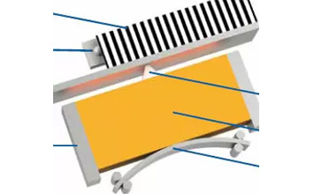
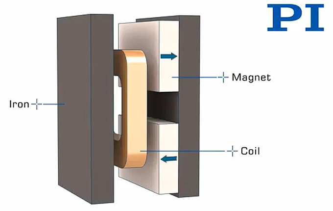
PILine® positioning systems are based on ultrasonic piezomotors that are capable of direct-driven linear motion. A piezoelectric actuator is preloaded against a runner using a coupling element (see Fig. 1).
Figure 1 Schematic design of a PILine® motor: The piezoelectric actuator is preloaded against the runner. Electrical excitement of the actuator causes oscillation. This oscillation is converted to forward motion which is then transmitted to the runner using a coupling element. The position of the runner is recorded by a stationary sensor (encoder), which counts the periods of a grating attached to the runner (Image: PI) 
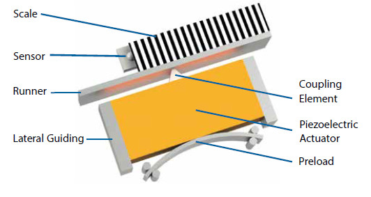
Electrical excitement of the piezoelectric actuator at its resonance frequency1 causes oscillation. Due to the preload, the actuator oscillation is converted to continuous feed motion by the coupling element, which moves the runner.
The preload also causes the drive to self-lock when at rest. The velocity of the motion can be adjusted by modifying the amplitude of the excitation and therefore the amount of power transferred to the runner.
Changes in position of the stage are detected accurately by an incremental, or in some cases, an absolute-measuring linear encoder. The number of counts recorded by the encoder is proportional to the distance travelled. Sub-nm resolution is possible using state-of-the art sensors and gratings.
Note that for accurate reproduction of the sensor resolution, the motor has to be operated in closed-loop mode.
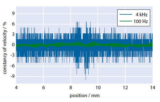
Direct measurement of the velocity is not possible with this method. However, by measuring the time Δt = t2 – t1 required for the stage to travel a distance Δs = s2 – s1, the velocity can be obtained from the relation v = Δs / Δt.
Bear in mind that the distance Δs varies depending on the sampling rate 1/Δt used, therefore different results are obtained for the constancy of velocity (= vactual / vset – 1), despite identical stage movement (see Fig. 2).
Figure 2 Constancy of velocity versus position; recorded several times at two different sampling rates. Small local changes in velocity have significantly more impact at high sampling rates (Image: PI) Depending on the particular area of application, a customer might be interested that the stage reaches the target destination as fast as possible (at the cost of precision), or as accurately as possible (with reservations on the time required). Both requirements are addressed in detail in the following chapters.
2.1 Stability: Self Clamping Principle
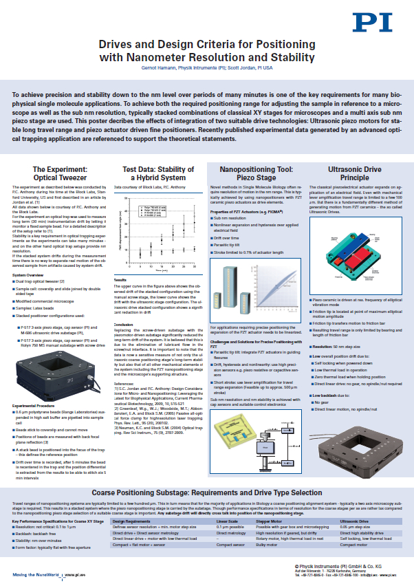
Velocity and resolution are not the only criteria for precision motion control applications. Due to the preload and the ceramic / ceramic drive principle, the ultrasonic motor acts like a brake when not energized. This feature is decisive for applications where long term stability is crucial, for example in super-resolution microscopy and imaging. Tests with ultrasonic motors in an optical trapping set-up show significantly better stability than screw driven stages, especially over long periods of time.
More information is available in the paper below.
Drives and Design Criteria for Positioning with Nanometer Resolution and Stability Learn more 3. Fast Positioning
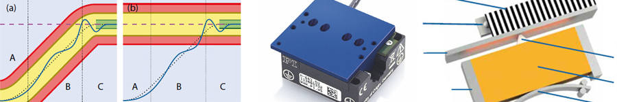
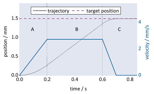
When targeting a position, the inbuilt profile generator of the PILine® controller (e.g. C-867) creates a velocity profile for the motor, which consists of three regions (see Fig. 3): (A) acceleration, (B) constant velocity, and (C) deceleration and settling.
Figure 3 Example of a position and velocity profile created by a PILine® controller. It can be divided into three regions: acceleration (A), constant velocity (B), and deceleration and settling (C) (Image: PI) Each of these regions can be tuned individually by adjusting the corresponding controller parameters. For better under- standing, the principles of the servo algorithm will be explained, before discussing individual parameters later in this chapter.
PILine® stages are usually operated in closed-loop mode, where a proportional-integral-derivative (PID) algorithm is used to compensate for trajectory deviations. Comparing the actual position (obtained from the sensor) with the commanded position returns the following error which serves as a process variable for the PID algorithm. Using the constantproportional, integral and derivative PID terms, the controller output is adjusted in an attempt to minimize the following error.
The controller features up to five independent sets of PID parameters (set 0 to 4). As depicted in Fig. 4, these PID sets are arranged concentrically around the commanded position or around the target position (default), depending on the window changing strategy (parameter0x4D).
The proportional, integral and derivative parameters should decrease with increasing PID set number. The number of parameter sets to be used can be configured with parameter 0x400.Operating with three sets is recommended. Each set of PID parameters contains two windows: window enter and window exit, specifying the activation area.
Figure 4 The enter and exit windows of a three PID set configuration are represented by different colors. The windows can be centered around the commanded position (a) or centered around the target position (b; default setting). The innermost PID set (0, green) is activated only after settling begins; i.e., when the commanded position is equal to the target position. Note that in (b), the outermost PID set (2, red) is already active before the actual position of the stage reaches the corresponding enter window (Image: PI) 
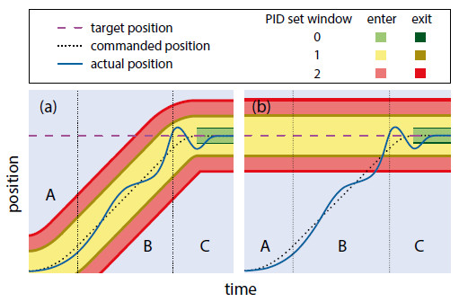
As soon as the actual position of the stage reaches one of the entry windows, the corresponding PID set is activated automatically. By definition, window exit has to be larger than window enter to prevent the parameters from switching back immediately. The window exit parameter of the outermost PID set is ignored by the PILine® controller, leaving this PID set active even when the stage exits the window.
PID parameter set 0 (0x401 to 0x407) plays the specific role of regulating the settling behavior – it is activated only after the commanded trajectory has finished (see Fig. 4). The other PID sets (1 to 4, 0x411 – 0x447) determine the behavior during stage motion.
3.1 Region A: Acceleration
In this region, the stage accelerates until it reaches the maximum velocity predetermined by the profile generator.
The acceleration region can be minimized by
- increasing the acceleration parameter
- adjusting the drive offset parameters
Please note that all of these parameters depend on ambient conditions and have to be determined individually for each area of application.
As a quick and simple first measure, try increasing the motor’s acceleration (0xB), which by default is set to a rather conservative value (see Fig. 5).
Figure 5 The positioning time can be reduced using higher acceleration values. The dashed lines mark the time of settling for an exemplary PILine® linear stage (Image: PI) 
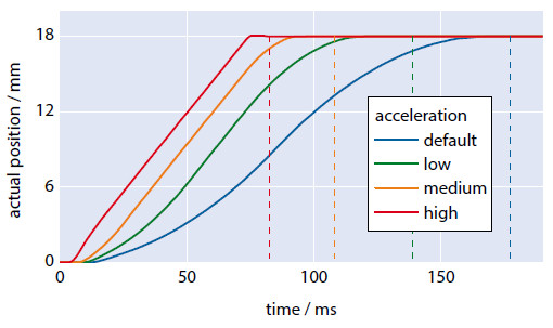
Note that higher acceleration can reduce the product lifetime.
Please make sure to monitor the motor output of the controller: under normal circumstances, the motor should run at a motor output of approximately 50 % of themaximum motor output parameter (0x9). The top 20 % of the motor output is intended as a control reserve. For this reason,avoid operation above a motor output value of 80 % to avoid damaging the motor.
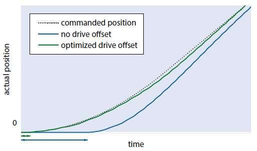
The second method of shortening the acceleration region involves adjusting the offset voltage parameters of the controller. Before the stage can start moving, stiction between the coupling element and runner has to be overcome. For that purpose, the controller gradually increases the motor output. The delay time associated with this process can be reduced by increasing the drive offset parameter (0x48), which sets the start value of the motor output voltage (see Fig. 6).
Figure 6 Adjusting the drive offset parameter reduces the time delay before starting (indicated by arrows), which is caused by initial stiction between coupling element and runner (Image: PI) 
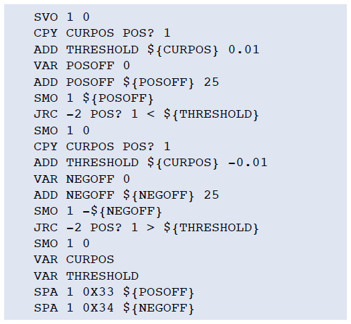
Additionally, compensation for direction-dependent load of the stage (e.g. when mounted vertically), is achieved by tuning the parameters motor offset positive (0x33) and motor offset negative (0x34). These offsets are applied together with the motor drive offset. Suitable initial values can be found and set using the following host macro in PIMikroMove:
Figure 7 Running this host macro in PIMikroMove will determine the motor output required to drive off, both in a positive as well as a negative direction. These values then are stored as positive and negative motor offsets (0x33, 0x34) in the volatile memory of the controller. 3.2 Region B: Constant Velocity
In this region, the stage has reached its constant maximum velocity.
The constant velocity region can be reduced by increasing the stage velocity(parameter 0x49).
In some cases, especially when covering short distances, the stage may go directly from acceleration (region A) to deceleration (region C), without reaching the maximum velocity. If so, try increasing the acceleration (0xB) and deceleration (0xC) parameters.
3.3 Region C: Deceleration and Settling
In this region, the motor decelerates as it approaches the target position.
The deceleration region can be minimized by
- increasing the deceleration parameter
- adjusting the integral term of PID set 2
- increasing window enter of PID set 0
Increasing the deceleration parameter (0xC) is similar to increasing the acceleration in region A, as explained in chapter 3.1.
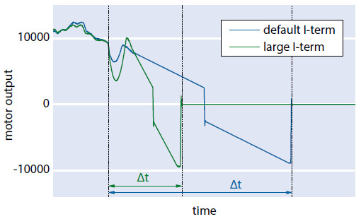
Faster deceleration can also be obtained by increasing the integral term of the second PID set (parameter 0x422). This increases the velocity of pulling the stage into the settling window (PID set 0), as depicted in Fig. 8.
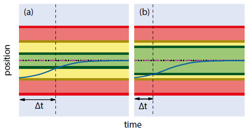
If accuracy is not of utmost importance, the window enter parameter of PID set 0 (referred to as “settling window”, (0x406) can be widened to achieve earlier settling, as shown in Fig. 9.
Figure 9 Zoom-in to the settling region of Fig. 4. Default settling window (a) versus increased settling window (b) leading to earlier settling (for a legend see Fig. 4) (Image: PI) 4. Accurate Positioning
When particularly accurate positioning is required, reservations on positioning speed have to be taken into account. Higher accuracy can be obtained by using a smaller settling window; i.e., by reducing the window enter 0 (0x406) and window exit 0 (0x407)parameters.
The achievable positioning accuracy is limited by the grating period of the scale, the accuracy of the sensor, and the interpolation factor of the sensor electronics. For higher accuracy consider acquiring:
- stages with finer grating periods
- controllers with internal interpolation
As mentioned in chapter 2, a sensor is used (see Fig. 1; also referred to as encoder) to determine the position and velocity of the stage. In PILine® positioning systems, optical and magnetic incremental and absolute sensors can be used depending on the required accuracy, energy consumption and cost efficiency. In most cases, optical incremental sensors are used. These sensors determine the distance to a given reference point by recording a periodic pattern (referred to as grating) on a scale.
The grating periods utilized range from a few to several tens of micrometers. Using two photodiodes with a 90° phase shift, two sinusoidal signals are generated allowing for detection of the direction of motion. These signals are then processed by an interpolation circuit which splits each period into several equally-spaced pulses. The final resolution corresponds to that of the grating period divided by the interpolation factor.
Using a PILine® stage with a state-of-the-art PIOne (PI Optical Nano Encoder) sensor with a sensor signal period of 0.5 μm and an interpolation factor of >1,000, sub-nm resolution can be achieved.
Typically, interpolators with interpolation factors of 256 to 8192 are integrated directly into the stage electronics. Some PILine® stages have a switch for bypassing this inbuilt interpolator. In this case, the output changes from internally interpolated A/B counts to raw sine/cosine signals, which can be processed further by an external interpolator.
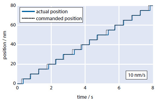
The new PILine® C-867.1U controller features an integrated interpolator with an interpolation factor of up to 20,000, enabling manifold increasing the resolution of your existing stages. Applications that require precise positioning as well as very slow-motion benefit from this gain in resolution (refer to Fig. 10).
Figure 10 Trajectory of a customized PILine® M-683 stage with a PIOne sensor, interpolated externally by a PILine® C-867.1U controller. The commanded position profile is reproduced very precisely (Image: PI) 5. Controlled Positioning with Priority on the Trajectory
PILine® motors feature a broad dynamic velocity range of 10 nm/s to > 100 mm/s, which can be subdivided into three characteristic ranges:
- Ultraslow motion (10 nm/s to 10 μm/s)
- Slow motion (10 μm/s to 1 mm/s)
- Fast motion (> 1 mm/s)
The peculiarities and challenges of each of those velocity ranges will be discussed in the following subchapters.
5.1 Ultraslow Motion (10 nm/s to 10 μm/s)
Positioning at ultraslow speeds is essential when scanning small objects; e.g., when using a microscope with a PILine® stage in manual mode. Customizing the PID and controller parameters according to the intended use is imperative for achieving optimum performance of the stage.
A key requirement for this velocity range is uniform motion. For this purpose, some PILine® controllers (e.g., the C-687.262) offer a so-called second phase actuation. In this mode, the unused electrode of the motor is driven by a secondary output stage; the amplitude can be set using the motor offset parameter (0x6F). Doing so will adjust the forward feed vector of the coupling element, which decreases the breakaway torque.
On the downside, forward force is reduced in this mode. The best results are achieved using motor offset values between 50 % and 70 % of the maximum motor output parameter (0x9).
Following errors, which occur particularly in this velocity range, have to be compensated by boosting the P-term of the current PID set to a very high value (refer to chapter 6). Assuming that the stage is well tuned, the actual trajectory can closely reproduce the generated profile as depicted in Fig. 11.
Figure 11 Ultraslow motion at 1 μm/s before and after P-term optimization. The optimized proportional term causes the stage to closely reproduce the commanded position profile (Image: PI) PILine® controllers also feature a regulating circuit for automatic excitation frequency adjustment, which may interfere with the PID regulation. Before beginning with optimization of the P-term, make sure that the automatic frequency search (0x52) is switched off. Furthermore, a slight increase of the output frequency (0x51) can prove to be beneficial when driving slowly.
5.2 Slow Motion (10 μm/s to 1 mm/s)
Typical applications for this velocity range include triggered image capturing or laser-cutting cells.
A rattling noise, created by a periodic coupling mode switching of the coupling element, may occur in this speed range. The noise might seem to be annoying; however, the cause of this is not harmful to the motor. It can be eliminated by driving the motor with a secondary phase using the motor offset parameter (0x6F), as explained in chapter 5.1. Using a secondary phase also reduces the position error as well as the required motor output.
5.3 Fast Motion (>1 mm/s)
This velocity range is mostly used for fast step-and-settle applications. Typical use cases are positioning lenses in a beam path or shutter applications. Here, the main requirement is fast and accurate positioning; the shape of the trajectory plays a subordinate role.
In most instances, the default settings of the controller can be adopted without the need for time-consuming customization. Furthermore, the use of two-phase actuation (motor offset) is not required and might in fact lead to slower final velocities and less forward force.
6. Driving Along a Trajectory with Minimum Position Deviation
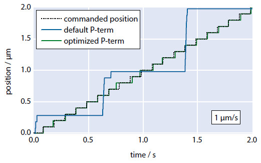
When minimum position error is required, the P-term of the active PID parameter set has to be adjusted according to the current velocity of the stage. The I- and D-term do not need to be changed; however, decreasing them might be beneficial in some cases. Fig. 12 shows the empirically determined P-terms of an exemplary PILine® stage, for which the minimum following error is obtained.
Figure 12 Exemplary P-term vs. velocity diagram of a PILine® linear stage, plotted on a logarithmic scale. Different values may apply to your stage (Image: PI) 
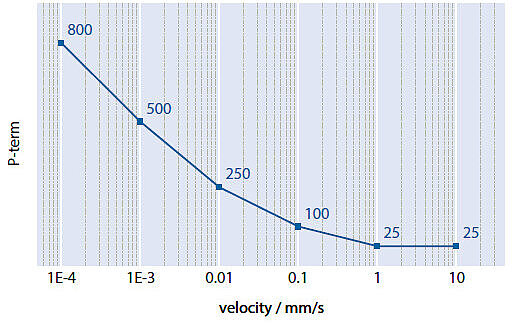
To obtain the smallest possible following errors regardless of velocity, a function adjusting the P-term to the current velocity can be implemented in all supported software environments, e.g. by using an empirical formula or a lookup table.
Author: Dr. Christian Benz is development engineer for piezomotor products at Physik Instrumente (PI) GmbH & Co. KG.
Blog Categories
- Aero-Space
- Air Bearing Stages, Components, Systems
- Astronomy
- Automation, Nano-Automation
- Beamline Instrumentation
- Bio-Medical
- Hexapods
- Imaging & Microscopy
- Laser Machining, Processing
- Linear Actuators
- Linear Motor, Positioning System
- Metrology
- Microscopy
- Motorized Precision Positioners
- Multi-Axis Motion
- Nanopositioning
- Photonics
- Piezo Actuators, Motors
- Piezo Mechanics
- Piezo Transducers / Sensors
- Precision Machining
- Software Tools
- UHV Positioning Stage
- Voice Coil Linear Actuator
- X-Ray Spectroscopy
USA / Canada
contact@pi-usa.usEAST
(508) 832-3456
MIDWEST
(508) 832-3456
WEST
(949) 679-9191 (LA Area & Mexico)
(408) 533-0973 (Silicon Valley/Bay Area) - Resources