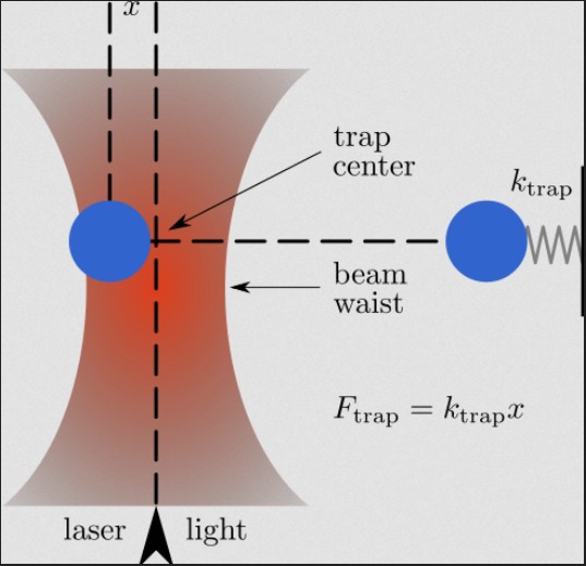
In October 2018, Arthur Ashkin was awarded the Nobel Prize in Physics “for the optical tweezers and their application to biological systems.” This was in acknowledgement of work that had started five decades earlier, when he was performing research at AT&T Bell Laboratories. For an optical communication project, he began investigating radiation pressure from a laser beam and how it acted on particles. In addition to the axial acceleration of particles that he expected, he noticed that small particles congregated in the center of the beam. He could even steer the particles around by sweeping the beam. The beam's puzzling tractor effect was soon understood both for very small (subwavelength) particles and for larger ones. The radial force that arises from the lensing of light through larger particles - combined with the Gaussian beam profile's significant gradient and the dictates of momentum conservation - pulls particles with a higher refractive index than their suspension medium towards the center of the beam. A similar net effect arises for smaller particles because the field gradient induces dipole moments in them.
The trap force is readily characterized, rather strong and easily calibrated, meaning that the technique is useful for quantitative studies of natural processes on the nanometer scale as well as for precise noncontact manipulation of objects as small as 5 nm.
There have been several generations of improvements to the technique. Early on, researchers used optical trapping to manipulate a wide variety of particles, including living viruses and cells, and to explore the physics of colloids. These endeavors led Steven Chu of Stanford University in California to his Nobel Prize-winning research into trapping atoms and to the dynamical characterizations of nanoscale molecular motors in living cells made by Stanford's Steven M. Block.
3D Optical Traps
Along the way, three-dimensional traps were devised, including the single-beam configuration that is the basis of today's most frequently encountered optical trapping setups. These have been integrated by users into commercial microscopes, in which an objective with a high numerical aperture tightly focuses the laser beam, establishing a 3-D gradient that traps particles axially as well as transversely.
Most recently, the novel properties of Bessel-profile beams and holographically generated arrays of beams have enabled precise parallel manipulation of mesoscale arrays of microscopic objects. Also, electronically controlled holographic gratings have emerged for establishing complex and useful configurations of light, and non-Gaussian modal structures and modified phase profiles have proved useful for trapping opaque or reflective particles, for imparting torque and for generating optical vortexes. Not a month goes by without another application emerging that impacts the fields of optical physics, materials science or biophysics.
As successive generations of researchers and entrepreneurs build on earlier research, equipment manufacturers have answered the call for increasingly sophisticated building blocks. Most optical trap setups remain homemade, although a few pioneering companies have staked out specific applications to provide preconfigured tools that include optical traps. Still, researchers generally build upon each other's designs, innovating incrementally. Many setups are based upon high-end commercial microscopes, although some are built from catalog optical components. Lasers are chosen to suit the particles being manipulated, and optical position-detection and imaging hardware are commonly added.
One constant has emerged, however: Relentless demands for increasing performance require precise relative positioning of the beam and the sample.
Beam and Sample Positioning
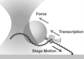
Some configurations adjust the optical trap by guiding the laser beam as it enters the microscope with steering mirrors or acousto-optic scanners. Positioning also can be achieved through translation of a plano-convex lens in the laser beam path, which provides axial positioning as well. However, many advancements have resulted from using nanoscale-precision translation stages to move the trapped object(s) with respect to the microscope structure, which facilitates the dynamic positioning of the trap and the calibration of trap forces. This in turn has facilitated insightful applications such as force and step metrology of individual transport and polymerase molecules in living cells, illuminating key biophysical processes which animate the most fundamental cogworks of life and disease.
Resolution, Repeatability and Stability
The researcher's choice of positioning mechanism thus emerges as critical. Resolution, repeatability and stability affect the capabilities of a setup due to the extraordinarily small dimensions and forces being investigated, but dynamic accuracy - the deviation of a rapidly actuated positioning system from the desired position at any instant in time - has gained importance because speed requirements have ramped up to keep pace with requirements for tracking, scanning and real-time alignment. For example, Brownian motion is an ever-present issue on the molecular scale, and since this confers random motion on nano- and mesoscale objects of interest, corrective motions may, in some applications, be performed to maintain alignment. Another example is in the motion studies of protein-editing RNA polymerase and transport molecules like kinesin-- the trap must be continually re-centered as the tethered molecule methodically inches its way along. Also factoring into equation are system bandwidths, interface throughput, servo following error and structural resonances. Each of these parameters represents a different potential bottleneck in the motion system and can limit overall system responsiveness and throughput and therefore its ability to keep pace with rapid application processes:
- System bandwidth refers to the overall responsiveness of a stage/controller combination and is most often impacted by amplifier and processor power;
- Interface throughput refers to the ability to issue commands and receive back information such as acknowledgements, status information, query responses, motion-complete signals and triggers;
- Following error is the system's ability to be where it is supposed to be at any instant as a motion executes. Servo design factors heavily into this; for example many servos lack notch filters to desensitize the servo from the stage's own resonant behavior, necessitating more cautious (and slower) servo settings and slower performance
- Structural resonances refer to the recoil and ringing that occur in loads and adjacent componentry when a nanopositioning stage is actuated rapidly. Since these are unobservable by the stage's internal position sensors, no combination of servo parameters can eliminate them without drastically slowing system behavior.
Fortunately, users benefit from recent technological developments driven not only by increasingly stringent research requirements but also by industrial demands in arenas such as semiconductors and defense. In a well-designed system, each of these bottlenecks can be addressed.


Integrated Stage Position Sensors
Position sensors are integral for ensuring repeatability and accuracy in a nanopositioning stage's movement. Piezoelectric drives, although capable of subatomic resolutions and >1000-g acceleration, exhibit an applied voltage vs. position curve that is nonlinear and hysteretic. Generally a linear relationship is desired so the precise commanded position can be repeatably achieved. Therefore, position sensors are integrated into the stages to provide the feedback necessary for an analog or digital servocontroller to eliminate hysteresis and nonlinearity.
A variety of sensors have been used over the years. Among the more economical are strain gauges, a class of devices that includes piezoresistive gauges. Such sensors are flexible films affixed either to the piezo stack or to the flexures of the stage and are capable of superb resolution. They infer the position of the moving platform (the workpiece) indirectly, which puts them at a disadvantage to capacitive sensors.

Capacitive Sensors
By comparison, capacitive sensors measure moving platform's position directly. This allows the user to know the position of their load in real time and with subnanometer precision. Capacitive sensors are composed of two diamond-machined plates of exquisite flatness, one affixed to the moving platform and one to the stationary frame of the nanopositioning stage for each axis. As the platform moves, it varies the gap between the plates, which changes the capacitance of the cavity. When excited by a precisely-controlled sinusoidal stimulation signal, this provides a sensitive measure of position with inherently superior stability and immunity to electromagnetic noise. They have emerged as the premium sensor for the toughest applications because of their unmatched combination of resolution, stability, accuracy, environmental insensitivity and bandwidth.
As Block and his Stanford colleague Keir C. Neuman noted in a review article, piezo-controlled stages permit three-dimensional control of the position of the trap relative to the trapping chamber, which has previously proved difficult or inaccurate. They go on to note that such stages enable such capabilities as accurately calibrated pico-newton force metrology and constant-force displacement metrology over the stage's full length of travel, eliminating the working range of the trapping-chamber position detector as a limitation. This has proven to be a key enabler for molecular-force studies and investigation of RNA transcription and editing mechanisms.
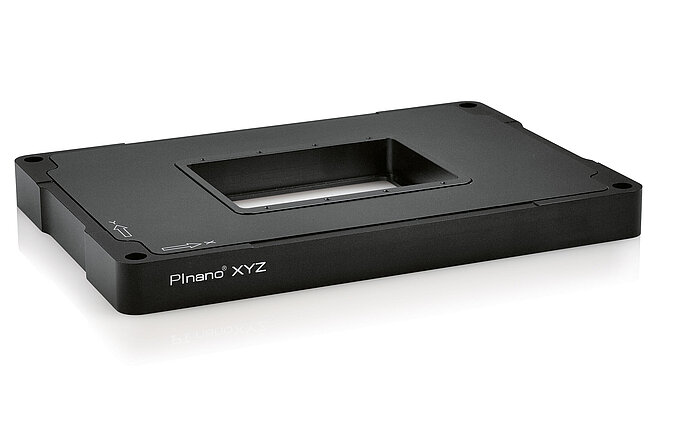
Stages using capacitive sensors also are ideal for parallel-kinematics mechanics, where several actuators move a single rigid work piece through several degrees of freedom by several actuators. A good example is an XY microscopy stage: such a stage could be constructed of a stack of two single-axis stages, but this results in orthogonality issues, dynamical differences between the top and bottom stage, extra thickness, reduced rigidity, and no possible way to compensate for undesirable orthogonal motion errors such as runout (deviation from straight-line travel). A superior alternative design is to actuate a single rigid motion platform with multiple actuators simultaneously, with capacitive sensors monitoring the platform's position from several different directions. In this way, the capacitive sensors automatically compensate for run-out and other orthogonal errors, and since only the workpiece moves, the moving mass is reduced compared to a stacked or nested configuration. This improves system responsiveness, motion dynamics and package size compared with nested or stacked approaches. Of particular relevance to optical trap applications are the low-profile, microscope-friendly multiaxis configurations facilitated by this design approach, since even the most advanced nanopositioning technology is useless if it won't physically fit into the optical setup.
Analog Servo Controllers
The stage's servo controller is another important part of the nanopositioning setup, and it can come in either analog or digital versions.
Analog controllers are capable of high speed and are very simple to use. Calibration is performed at the factory and fixed in the system; the electronics and motion device are therefore generally matched together. The position command input to the controller can be a voltage or a digital command sent via a USB, RS-232, IEEE-488 or proprietary high-speed serial interface. The best interface is not necessarily the one with the highest data transfer speed, because piezo servo controllers and motion controllers typically send and receive only a few characters at a time. Exact timing and minimal latency is more important for virtually all nanopositioning applications, particularly in time-critical tracking and scanning applications where the motions must be tightly coordinated with metrology or other processes.
In the case of an analog servocontroller with an analog voltage command input, the input voltage maps linearly to position. For analog controllers equipped with a digital communications interface, the incoming command is converted to a voltage input to the servo circuit by an internal digital-to-analog converter.
Most commonly, a digital-to-analog converter card installed in the user's PC provides the position command voltage for an analog servocontroller. For example, multifunction cards and applications software written with LabVIEW from National Instruments of Austin, Texas, are often used in optical trapping applications, and the availability of well-designed driver libraries and knowledgeable staff is an important starting point for selecting positioning equipment.
Analog interfacing is fast, with negligible latency, and available tools make it easy to program waveform generation, such as to perform force metrology for trap calibration. It is straightforward to program intelligence into the trap-control software, including tightly integrated machine vision for visualization, analysis and position tracking, and for position and force sensing. Synchronization between voltage outputs and data acquisition is easy to arrange, making it straightforward to tightly couple motion and metrology processes. Such is not always the case with commands sent via digital communications interfaces, unless they are based on a real-time protocol. On the other hand, servo controllers with the latest communications interfaces offer internal functionality, such as waveform generation plus synchronization lines, for integration with other instruments so that motion, metrology, video and other processes may be coordinated with good timing accuracy and responsiveness.
Importantly, the resolution of the internal digital-to-analog converters (DACs) that are integrated into the latest analog servocontrollers can be greater than the resolution of available PC converters and multifunction cards. Twenty-bit internal converters are increasingly common, which gains importance as increasingly longer travel piezo devices are introduced - devices with travel exceeding 1000x1000µm are now available. The "bitness" of the converter defines how small a motion can be commanded by the following formula:
Resolution (µm) = Travel (µm) / 2bits
Popular digital-to-analog converter and multifunction cards typically top out at 16 bits, or 65,536 possible addressable positions for the piezo nanopositioner. The resulting position resolution would seem to pose significant limitations for applications with nanometer sensitivities such as optical traps. Fortunately, HyperBit, a patented technology from PI (Physik Instrumente) L.P. of Auburn, Mass., provides additional subdivision of the DAC resolution to improve positioning resolution by many bits - up to two orders of magnitude - with no loss of bandwidth or accuracy and with ready compatibility with existing user programs and most converter hardware. Compatible with popular lab automation hardware and software from National Instruments and other manufacturers, this technology breathes new life into analog-interfacing setups for long-travel applications.
Digital Servo Controllers
Compared with analog servo controllers, digital controllers provide continuous microprocessor or DSP analysis of the position feedback, with continuous digital updating of the voltage applied to the piezo. The position sensors are sampled at high speed by an analog-to-digital converter, often with oversampling and statistical manipulation to enhance resolution and reduce noise. This information is then compared with the desired instantaneous position in N-space, where N is the number of axes under control. In the most advanced units, when driving a parallel-kinematics mechanism, the axes can be physical or virtual, and complex path planning and coordinate transformation can be handled automatically, for example to tilt or rotate about the trap's waist.
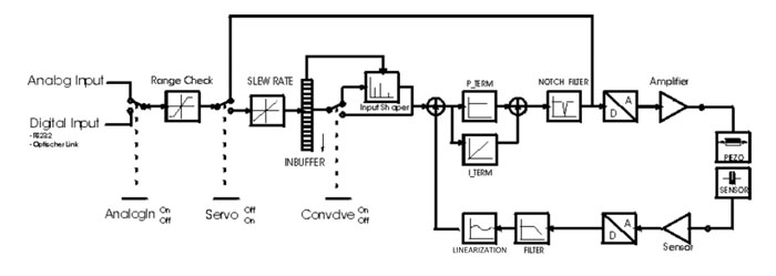
The controller's internal digital-to-analog converters are continuously updated based on the calculations -- typically performed by a fast digital signal processor -- and which can include sophisticated filtering algorithms. Linearization and calibration also are performed digitally; servo parameters therefore can be easily updated by software. High-end digital controllers actually read calibration information that is stored in the motion device itself, meaning that matching the motion device and controller is often unnecessary. The processor-based architecture of the controllers facilitates such features as waveform generators and advanced feed-forward techniques that can eliminate following errors in programmatic scanning and patterning operations-- errors which would otherwise reduce the accuracy of the scanning and patterning.
Note that the digital-to-analog converter resides "inside" the servo loop in digital controllers. This is an important distinction, because DACs can drift, particularly in the case of high-bitness units. DAC drift within a servo loop is automatically compensated by the servo. By comparison, a DAC located outside the servo loop (as in the case of an analog controller with internal or external DAC) will cause unwanted motion when it drifts.
The inherent stability of digital controllers is a great benefit, but only so long as the internal digital-to-analog converter is of high resolution. Some units utilize comparatively low-bitness converters and rely on a slow servo bandwidth to interpolate between adjacent bits, achieving the desired position. The resulting dithering motion and slow responsiveness is unacceptable for optical trapping applications.
Common Elements and Solutions
Since positional stability is important for most optical trap applications, which can be sensitive well into the subnanometer realm, all sources of positional noise and instability should be proactively addressed. Cables and fluid and vacuum piping must be carefully routed and clamped to prevent transmission of vibrations, especially from fan-cooled equipment. The quality and stability of the nanopositioning stage can be no better than the stability of the coarse stage and supporting structure, so these components should not be skimped.
If high-dynamic (rapid, sharp-edged) actuation is an application goal due to tracking or scanning needs, the possibility of motion-driven ringing in the structure, optics and load should be considered, suggesting an analog or digital motion controller integrating Input ShapingR from Convolve Inc. of New York. Or, if programmatic scans and patterns are part of your application, the consequences of following errors should be explored. For example, a popular trap force calibration procedure is to impart a rapid dithering motion of the trapped particle, such as the dielectric beads used to tether molecules of interest. The viscous fluid medium imparts Stokes drag forces on the trapped particle. The well-understood Stokes force allows calibration of the trap force profile based on the particle's deflection by the scanning. Since the accuracy of this calibration depends on the fidelity of the scanning motion, the calibration can be enhanced by eliminating servo following error using a digital servocontroller with PI's digital dynamic linearization function.
Electrical noise also can be an issue in sensitive setups. Switcher power supplies (which are used in even very costly lasers) can be troublesome sources of noise, and noise in the servo controller - particularly in its amplifier - can affect stability.
Interface timing indeterminacy is another important consideration when selecting a controller. RS-232, USB and IEEE-488 allow command throughput from the high dozens to low hundreds per second. However, programming technique can have a profound effect on throughput, and timing indeterminacy resulting from handshaking and background operating system activities can add unpredictable milliseconds to command responsiveness.
Proprietary digital interfaces can offer faster - well into the kilohertz range - and more deterministic communications than general-purpose communications interfaces, often surpassing the motion bandwidth of the system. Specialized interfaces with command cycle times in the microsecond range also are available for some controllers. Analog interfaces, of course, can be rapidly updated by adding a digital-to-analog converter card to the user's PC. In all cases, note that a faster interface does not necessarily result in a more responsive system. The interface is just one potential bottleneck. The resonant frequency of the loaded stage is a fundamental metric of system throughput, as are the controller's amplifier current and slew-rate capabilities.
Conclusion
As Louis Pasteur noted, "chance favors the prepared mind." The evolution of the optical trap into an indispensable and diversified tool for manipulating, sorting, characterizing, fabricating and organizing living and inorganic matter without contact and noninvasively is a testament to the ingenuity of three generations of scientists. Supporting their endeavors are an ever-broader wealth of building blocks that are the foundation of tomorrow's applications, promising to affect every facet of life by enabling new materials, addressing environmental concerns, releasing new forms of energy and curing diseases.
As Pasteur also noted, "Let me tell you the secret that has led me to my goal: my strength lies solely in my tenacity" - a quality in ample supply in this field.


Blog Categories
- Aero-Space
- Air Bearing Stages, Components, Systems
- Astronomy
- Automation, Nano-Automation
- Beamline Instrumentation
- Bio-Medical
- Hexapods
- Imaging & Microscopy
- Laser Machining, Processing
- Linear Actuators
- Linear Motor, Positioning System
- Metrology
- Microscopy
- Motorized Precision Positioners
- Multi-Axis Motion
- Nanopositioning
- Photonics
- Piezo Actuators, Motors
- Piezo Mechanics
- Piezo Transducers / Sensors
- Precision Machining
- Semicon
- Software Tools
- UHV Positioning Stage
- Voice Coil Linear Actuator
- X-Ray Spectroscopy