Industrial Safety Device for Hexapod 6-DOF Motion Systems / Parallel Robots
How to Connect a Safety Light Barrier to a Hexapod System

1 Motivation
Effective workplace safety measures are especially important in manufacturing environments when machines carry out fast movements with large forces. Physical barriers, such as fences that spatially separate people from machinery, are common and easy-to-integrate solutions. However, if mechanical systems cannot be installed or if the work process is influenced by them, contact-free safety concepts such as a light grid or a light curtain can be used. A light curtain forms a close-meshed protective field and, therefore, secures the access to the danger zone.
Hexapod robots are multi-axis positioning systems with a limited workspace that can often be safely integrated into industrial setups. However, if people can move into the workspace of the hexapod or of the setup on the hexapod platform then a safety measure must be set in place.
This blog explains:
- when it is useful and necessary to use a safety device;
- how a safety light barrier (or light curtain) works;
- how the risk assessment for hexapods is carried out;
- how the safety device can quickly be integrated in the controller environment.
1.1 Parallel-Kinematic Hexapods Compared to Serial-Kinematic Systems
Serial-kinematic systems consist of individual axes or actuators that build on one another, which means that they are mechanically connected in series. For example, a platform-bearing Z axis can be mounted on a Y axis, which in turn can be mounted on an X axis (Fig. 1) and so on.
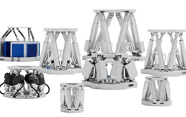
In hexapods, all six actuators act directly on a single platform. This allows a considerably more compact setup than is the case with serially stacked multi-axis systems.
Since only a single platform is moved, which is also often equipped with a large aperture, the mass to be moved is considerably smaller. This results in considerably improved dynamics.
In addition, hexapods exhibit higher accuracy since they usually do not contain guides with corresponding guide errors and the errors from the individual drives do not compound. Since the cables are not moved with the platform, the precision is not influenced by corresponding friction or torques. In addition, the parallel structure increases the stiffness and thus the natural frequencies of the overall system as well.
In stacked systems, however, the lower drives not only have to move the mass of the payload, but also the mass of the drives that follow, along with their cables. This reduces the dynamic properties. Guiding errors that accumulate on the individual axes also impair accuracy and repeatability.

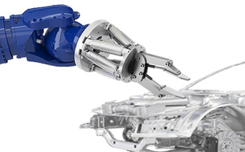
1.2 Fields of Application for Hexapods in Automation
Manufacturing and quality assurance processes in electronics production, mechanical engineering, and the automotive industry increasingly require compact multi-axis positioning systems. At the same time, the requirements for accuracy are also increasing.
Depending on the model, parallel-kinematic hexapod robots can move and position tools, workpieces, and complex components with masses ranging from a few grams, several hundred kilograms, to even several tons in any spatial orientation with high precision.
The PI hexapod controller with integrated EtherCAT® interface makes it easy for users to integrate hexapods into automation systems without having to do challenging kinematic transformations.
An essential feature of hexapods is the freely definable reference coordinate systems for the tool and workpiece position (Work, Tool). This allows the movement of the hexapod platform to be specifically adapted to the respective application and integrated into the overall process.
1.3 Safety-Relevant Applications
Generally, the risk of injury from hexapods, designed for precision positioning, is low because of the relatively low speed and the limited range of movement.

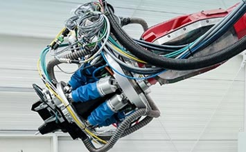
The situation is different for dynamic motion hexapods (see Fig. 3) because of their high speed and acceleration which can become a hazard for people who work in their immediate vicinity and can’t react quickly enough to avoid an impact. When a collision occurs high impulse forces due to mass inertia can cause harm. A safety system can protect people and minimize this risk of injury.
For these situations, PI provides hexapod controllers that feature a motion stop input (e.g. model C-887.522). The input is used for connecting external hardware (e.g. push buttons or switches) and it deactivates or activates the power supply of the hexapod drives. However, the motion stop socket does not offer any direct safety function in accordance with applicable standards (e.g. IEC 60204-1, IEC 61508, or IEC 62061).[2]
Hereafter, the integration of a light barrier (or safety curtain) in the control of the hexapod is described. The light barrier itself is compliant and approved in accordance with EN/IEC 61508 and EN/IEC 61496-1/-2.

2 Function of the Light Curtain
Safety light curtains are made of an emitting (transmitting) and a receiving unit. In the emitting unit, light sources that radiate toward the receiving unit are arranged at an even distance from each other (e.g. LEDs). The receiving unit is equipped with detectors in the same arrangement (e.g. photodiodes), each being responsible for the detection of its opposite light source. The resolution, i.e. the distance between the light sources, determines the level of protection provided (finger, hand, or body protection).
If one of the light beams is interrupted, the light barrier outputs the information via two so called OSSD (Output Switching Signal Device) outputs, which nowadays are standard for barrier-free safety devices. In the standard state, the outputs are at 24V and fall to 0V briefly and asynchronously from each other for the purpose of self- monitoring. To be able to interpret the output signals, a suitable and certified safety relay is required that switches off or stops the machine movement in the event of a failure.
3 Safety Requirements and Risk Assessment
Different things need to be considered when selecting and dimensioning the safety device.
1. The relevant EN ISO 13849-1 standard specifies the safety levels for the components used.
2. With the EN ISO 13855 standard, the minimum distance between the safety device and the danger zone is calculated.
3. Depending on the degree of protection, the minimum distances need to be increased accordingly.
The safety level is defined as described in the EN ISO 13849-1 standard. With this standard, a tree diagram can be used to determine the safety level that a system must meet. In Fig. 4 the risk diagram according to the EN ISO 13849-1 standard is depicted. To reach a defined safety level, all safety components must meet the requirements of that level.[1]

Severity of the injury | S |
Minor injury (normally reversible) | S1 |
Serious injury, including death (normally irreversible) | S2 |
Frequency and/or duration of the exposure to the hazard | F |
Seldom to more often and/or short duration | F1 |
More frequent to continuous and/or long duration | F2 |
Possibilities for avoiding the hazard | P |
Possible under certain conditions | P1 |
Hardly possible | P2 |
Fig. 4 Risk diagram and evaluation criteria according to EN ISO 13849-1.
The minimum distance between the safety device and the danger zone is calculated with the EN ISO 13855 standard. This dimension is important to be able to define the maximum range the light barrier must monitor. It should be noted that different speeds of approach apply to the different degrees of protection (person, hand, or finger). Depending on the degree of protection, the required distance may have to be increased as necessary.
The safety distance for optoelectrical safety devices for hand and finger protection is calculated according to EN ISO 13855. For this purpose, an approaching speed of 2000 mm/s is taken into account. Depending on the degree of protection the safety distance must be increased accordingly. For example, when protecting a whole person, it is possible to grab through the light barrier since the distance between the beams is large. Therefore, the safety distance has to be increased by 850 mm (length of the arm). This is also the case when the safety device is not high enough and a person could reach above or below it [1]. For our test implementation, a close-meshed light barrier with a resolution of 30 mm was chosen and, therefore, the safety distance did not need to be increased.
In the test setup, it was assumed that for a speed of 100 mm/s, the required stopping distance for the hexapod was 3 mm. Using the following formula (applies to light barriers with a resolution of < 40 mm):
S=v(t1+t2)+8(d−14)
Where the safety distance is S, v is the approaching speed, t1 and t2 are the triggering time of the electronics and braking time of the machine, d is the resolution of the light barrier. For our test setup, this resulted in a safety distance of 316 mm from the hexapod.

4 Implementation in the Laboratory

4.1 Mechanical Setup
Thanks to the three deflecting mirrors, the mechanical alignment of the components of the safety light barrier can be efficiently achieved with only one laser that emits light in the visible range. At the beginning, all three columns need to be adjusted vertically to the surface using setscrews. Following that, the laser can be mounted to the emitting and receiving unit and then one column after the other can be centered to each other.

The schematic alignment can be seen in Fig. 6 in the plan view. The laser beam can be seen when a paper is placed in between the mirrors. This is then centered on the mirrors and finally aligned with the receiver. When the emitter and the receiver are connected electronically, the LEDs on the receiver show that the alignment was successful.
4.2 Integration with the Electronics
The supply line between controller and hexapod is disconnected and then switched via the relays of a safety relay. Thereby, Stop category 0, per IEC 60204-1 is implemented, and the circuit offers the safety characteristics described in the EN ISO 13849-1 standard. The outputs of the light barrier are connected to the input contacts of the safety relay and, if required, an emergency stop switch can be connected in series. This is unproblematic from a safety point of view since series connection does not endanger safety.
Various options exist for resetting the safety relay after it was triggered. The easiest solution is an automatic start by applying 24 V to the reset/start contact. For a manual start, a button can be installed between the 24 V source and the contact. An additional feedback loop monitoring can be implemented via two relays with NC contact, which are each connected in series to the button. Feedback loop monitoring ensures that resetting is only possible when the safety relay switched before the failure. The coils of the relays must, therefore, be connected to the safety contacts of the safety relay.[3]
The information has to be passed on from safety relay to controller so that the program stop can be uniquely traced back to the safety device, the light curtain. In the test setup, an auxiliary output, which can also be used to display the status, is connected to the I/O connection of the controller via a further relay. This I/O connection has digital inputs as well as +5 V and GND outputs. These can be connected with a changeover contact on the relay in such a way that the controller has a high or low signal at the digital input, which can then be queried in the program.
The wiring is depicted in Fig. 7.

4.3 Implementing the Safety Function in the GCS Software from PI
In this chapter, an example is shown of how the safety function can be implemented when written in the Python programming language for the PI Python library. It is always possible to choose a different software solution or to use a PLC to connect the hexapod, for example, via EtherCAT. The PI Python library facilitates the use of the General Command Set (GCS) from PI. GCS offers a standardized set of commands that is independent of the connected controller or the drive principle used.
When using Python, each controller error throws an exception in the running program as soon as the next GCS command is executed. A controller error occurs, for example, when the motor voltage is disconnected by the safety circuit. This is why, in Python, try-except blocks can be used to ensure a controlled continuation of work after the activation of the safety function.
In the following example, a Python program is shown which moves the hexapod in an infinite loop in the Z axis. After the safety relay is triggered, the program tries to switch the hexapod's servo back on. The safety relay can be reset to its normal operation by pushing the reset switch. The hexapod controller keeps retrying to switch on servo. This only succeeds when the safety relay returns to normal operation while no new controller error has occurred.

4.4 Parts for Test Setup
In Table 1, 2, and 3 all required parts are listed for the safety light barrier described in this paper.
Table 1: Parts list for safety light barrier (Pilz GmbH)[3]
Item | Order no. | Quantity |
PNOZ s3 24VDC 2 n/o | 750103 | 1 |
PSEN op2H-s-30-075/1 | 630724 | 1 |
PSEN op Protective Column-090/1 | 630951 | 2 |
PSEN opII mirror column-090 Set | 632008 | 3 |
PSEN op cable axial M12 4-p. shield. 3m | 630303 | 1 |
PSEN op cable axial M12 5-pole 3m | 630310 | 1 |
PSEN op Protective Bracket-4/1 | 630956 | 2 |
Table 2: Other electronics
Item | Quantity |
24V power adapter | 1 |
Relays with changeover contact | 1 |
Relay with NC contact | 2 |
Emergency stop switch and reset button control line | 1 |
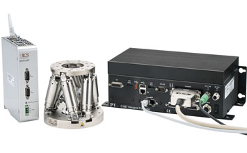
Table 3: PI mechanics and electronics[4]
Item | Quantity |
H-840.D2 hexapod mechanics | 1 |
C-887.522 hexapod motion controller | 1 |
C-887.MSB motion stop box | 1 |
5 Summary
The risk assessment for the hexapod in the test setup was carried out according to the EN ISO 13849-1 standard. As a suitable safety device with the highest degree of protection (finger), a safety light barrier (or light curtain), was set up around a hexapod and integrated into the controller circuit. As an example, programming with the help of the PIPython library enabled a fast and reliable startup. The Stop category 0, per IEC 60204-1 safety function was, therefore, successfully implemented.
6 Sources
Authors
- Dr. Christian Sander, Senior Expert for Hexapod Development at PI
- Jens Matitschka, Design Engineer for Hexapod Development at PI
Valid Standards
EN ISO 13849-1 „Safety of machinery - Safety-related parts of control systems – Part 1"
EN ISO 13855 „Safety of machinery - Approach speed of parts of the body for the positioning of safety devices"
[1] Neudörfer, Alfred: Konstruieren sicherheitsgerechter Produkte. Berlin, Heidelberg : Springer Berlin Heidelberg, 2016 — ISBN 978-3-662-49818-7
[2] Siemens AG: Einführung und Begriffe zur funktionalen Sicherheit von Maschinen und Anlagen ( Nr. E86060-T1813-A101–A5). Nürnberg, 2010
[3] Pilz GmbH & Co. KG: Das Sicherheitskompendium, 5. Auflage ( Nr. 775 740 8-8-1-0–100). Ostfildern, 2017
[4] Physik Instrumente (PI) GmbH & Co. KG: PI Hexapoden.
EtherCAT® is a registered trademark and patented technology licensed from Beckhoff Automation GmbH, Germany.

Blog Categories
- Aero-Space
- Air Bearing Stages, Components, Systems
- Astronomy
- Automation, Nano-Automation
- Beamline Instrumentation
- Bio-Medical
- Hexapods
- Imaging & Microscopy
- Laser Machining, Processing
- Linear Actuators
- Linear Motor, Positioning System
- Metrology
- Microscopy
- Motorized Precision Positioners
- Multi-Axis Motion
- Nanopositioning
- Photonics
- Piezo Actuators, Motors
- Piezo Mechanics
- Piezo Transducers / Sensors
- Precision Machining
- Semicon
- Software Tools
- UHV Positioning Stage
- Voice Coil Linear Actuator
- X-Ray Spectroscopy