1 Introduction
Electromechanical conversion in piezoceramic solid-state actuators can generate highly dynamic motion. Rise times significantly less than 100μs and repetition frequencies in the kHz range are state of the art and are used in applications such as fuel injection, ink jet printing, adhesive dispensing, active vibration damping or in adaptive tools. The control frequency is generally limited by the heat generation of the actuator due to its dielectric losses and can be increased by passive and active cooling measures.
This paper describes the results of self-heating tests for various cooling measures. In addition, an improved hermetically sealed piezoceramic multilayer actuator suitable for liquid cooling is proposed. With a newly developed amplifier, nominal displacement of 35µm at 3,300Hz was demonstrated with actuator temperatures not rising above 80°C.
Piezoelectric actuators have become the leading electromechanical solid-state actuator technology in the last 25 years [1]. The active principle is based on the inverse piezoelectric effect, in which a mechanical deformation is produced by the application of an external electric field in poled piezo-ferroelectric ceramics. The resulting deflection signal is a superposition of contributions from purely piezoelectric ionic displacements and reversible ferroelectric reorientations [2].
In order to increase the limited induced displacement of individual piezoceramic layers, actuators are generally produced from many stacked layers. These multilayer actuators are used in different applications including precision motion control. Advantages are friction-free movement with almost infinitely high resolution, high blocking forces, compact design, and high energy efficiency in quasi-static operation [3].
Other applications are based on the extreme dynamics of the generated mechanical signals. In addition to ultra-short mechanical switching times in the microsecond range, piezo actuators have been used with repetition frequencies of hundreds of Hz at full displacement amplitudes [4]. Application examples include piezoelectric inkjet printers, piezoelectric fuel injection systems, dispensing devices, adaptive tools, and micro pumps [1].
At large signal amplitudes, the maximum achievable repetition rate (operating frequency) of piezo mechanisms is often limited less by the mechanical resonant frequency than by the self-heating effect of the actuators due to their internal dielectric losses. The optimum utilization of piezoelectric multilayer actuators in applications such as adaptive systems and active vibration cancellation operating with bandwidths in the kHz range requires an efficient way to dissipate the resulting heat away from the actuator. Additional performance gains can be made by piezoceramic multilayer actuator components that have been optimized for highly dynamic applications.
2 Basics
2.1 PICMA® Multilayer Actuator Technology
PI Ceramic (PIC) has access to a wide range of technologies for producing piezoceramic actuators. The techniques can be divided into two categories: 1) pressing/sintering (bulk) technology, 2) film technology [5]. Using bulk technology, ceramic cylinders or blocks are pressed and sintered, then separated into discs, plates or tubes, provided with electrodes and glued to form actuators such as benders or linear piezo stacks (PIC product lines: PICA stack, PICA shear, etc.). The minimum layer thickness is limited to approx. 200μm (typically 500μm) because of the machining processes and the fragility of the ceramic material. The layer thickness puts the nominal drive voltages in the range of 250V to 1000V, often referred to as high voltage piezoceramics (HVPZT).
Tape casting-based production technologies (film) allow significantly lower operating voltages. Ceramic-filled polymer films in the 20µm to 60µm range are produced in the casting process then screen-printed with electrodes, stacked, and pressed. Only then are the components sintered and turned into the final products. Using ten-fold thinner layers allows the nominal operating voltages to be reduced to a range of 60V to 120V. Actuators based on tape casting technology are often referred to as multilayer actuators or low voltage piezoceramics (LVPZT).
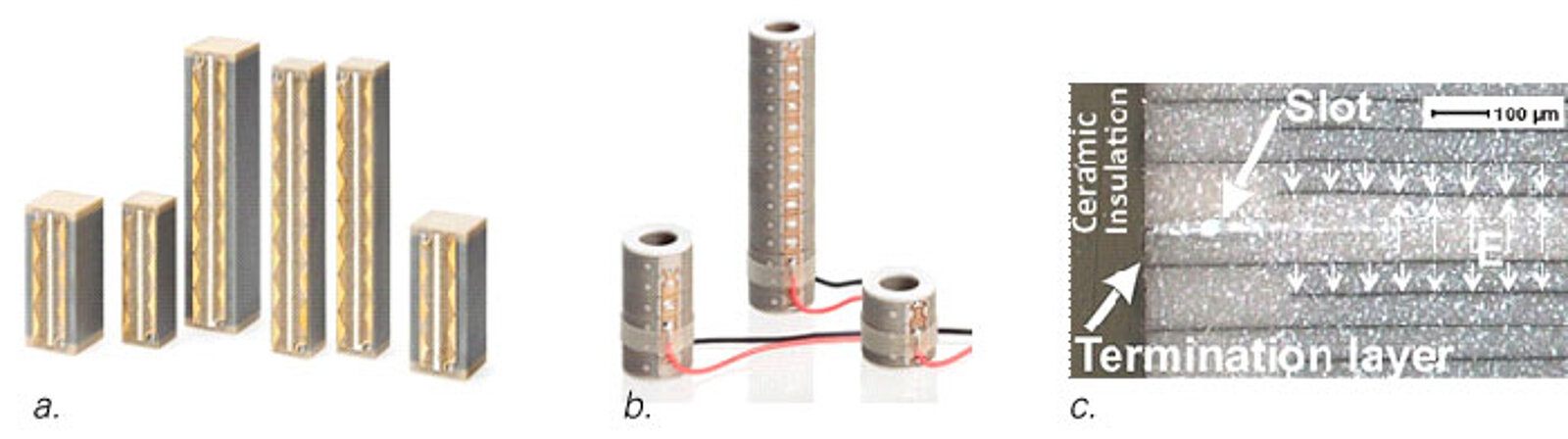
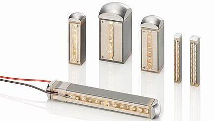
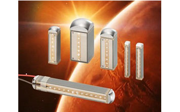
PIC product lines manufactured in multilayer technology, bear the trade name PICMA® (PI Ceramic Multilayer Actuators). In addition to multilayer bending actuators (PICMA® Bender) and small chip actuators (PICMA® Chip), stacked actuators (PICMA® Stack) with square and round cross-sections are offered (Fig. 1).
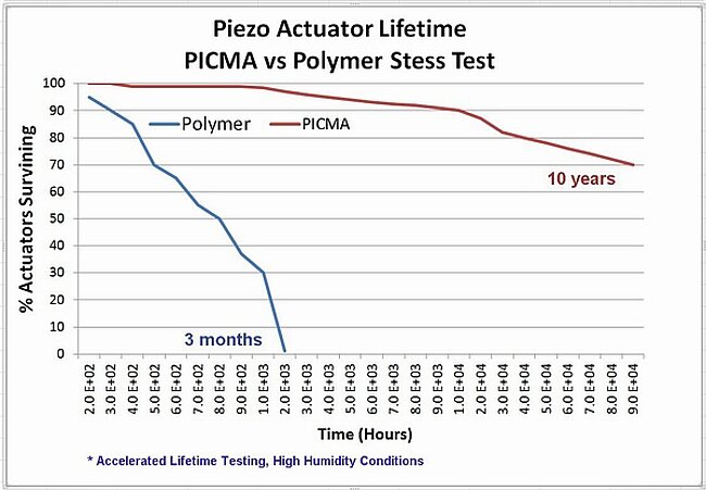
The internal electrodes of all PICMA® actuators are insulated by a thin ceramic foil covering the electrodes without significantly limiting the deflection. This patented process increases the lifetime of the actuators – especially in static and quasi-static applications with mostly DC voltage operation (Fig. 2) – by several orders of magnitude compared to traditional polymer-insulated actuators (conformal coatings) [6].
As a result, the wide use of piezoelectric actuators for nanopositioning applications in semiconductor and bio-technology fields such as nano-lithography, super-resolution microscopy, and gene sequencing was made possible [7].
The reliability of piezoelectric actuators in dynamic applications with high repetition rates is significantly influenced by the crack formation in the brittle ceramic composite. In order to control this cracking and thus guarantee the service life in dynamic applications, patented pre-cracks, so-called slots, are introduced into PICMA® Stack actuators. In addition, a special electrode design ensures that extremely high switching currents in the double digit ampere range (for ultra-fast rise times) are feasible without delamination (Fig. 1a) [6].
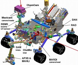
The robustness of these electrodes, as well as the absence of polymeric substances in the structure of the actuator, also make it possible to overcome severe temperature fluctuations and for some applications to even exceed the temperature range of -40°C to +150°C. PICMA® stack actuators are used, for example, in the Curiosity Mars rover after passing 1011(100 billion) cycles of life testing without failures and in large quantities in particle accelerators, at cryogenic temperatures of 4k to 10 K, also after enduring 20 years of accelerated life testing. In both cases, PICMA® actuators were selected over competing products after extensive testing and evaluation procedures [8,9].
2.2 Self Heating and Losses
The maximum repetition rate of piezoelectric actuators under dynamic stress can be limited by the resonant frequency of the mechanical system, by the self-heating of the actuator, by the limitation of the electrical driver power, and–in case of closed-loop operation–by the control bandwidth.
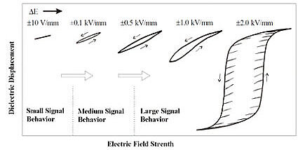
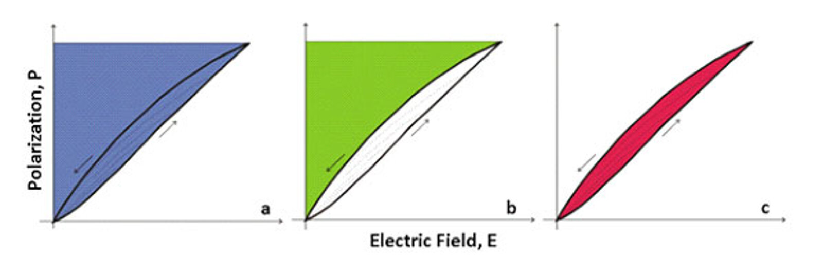
In open-loop, large-signal driving applications, the self-heating effect of the actuator usually limits the repetition frequency to a few hundred Hertz. The main cause of heat generation is the dielectric loss in the actuator during operation below the first mechanical resonant frequency. Piezo actuators have hysteresis-dependent dielectric characteristics at higher drive field strengths, due to the reversible ferroelectric reorientation (Fig. 3).
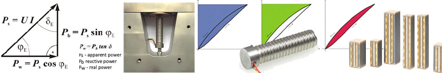
During the charge cycle, dielectric energy flows into the actuator (Fig. 4a). During the discharge, a large part of this reactive energy flows back into the driving amplifier (Fig. 4b). The content of the hysteresis area is the fraction of the energy that is converted into heat each cycle (Fig. 4c).
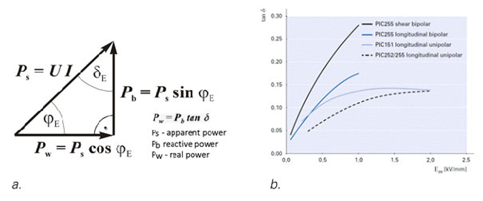
In order to describe the proportion of the dielectric losses in capacitive components, the dielectric loss factor tan is generally used as the ratio of the resulting thermal effective power Pw and the reactive power Pb (Fig. 5a).
5b) shows the strong dependency of the loss factor on the drive field strength for various piezoceramic materials and actuator drive modes. In the case of unipolar operation at nominal field strength or voltage, approx. 10% to 15% of the reactive power used is converted to heat, depending on the piezo material [10].
In order to extend the application range of the actuators towards higher repetition rates, it is necessary remove the heat generated in the actuator. Investigations with 5x5x36mm³ PICMA® stack actuators have shown that only 20% of the heat energy is dissipated via the top and bottom end faces, if the actuator is surrounded by free flowing air. The remaining heat escapes through the jacket surfaces.
In real-world applications however, actuators are typically installed in narrow housings, with negligible convection cooling due to limited air volume. Forced cooling with compressed air or heat-conducting paste fillings have become established as cooling measures of the jacket surfaces.
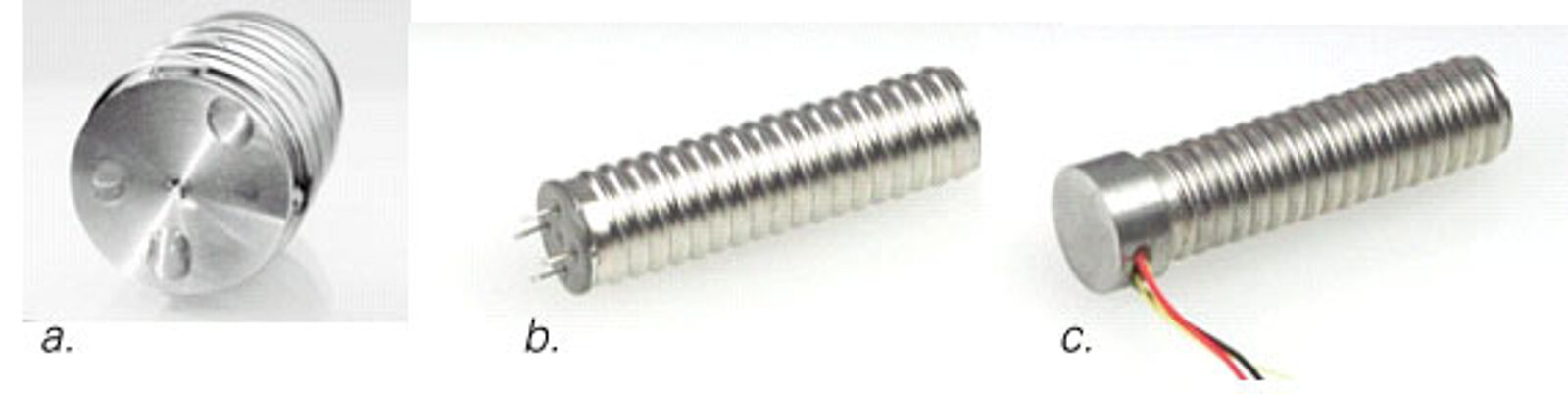
For harsh industrial environments, hermetically encapsulated PICMA® actuator products have been developed (Fig. 6). Encapsulation in a stainless steel housing improves the robustness of the ceramic actuator and protects it against environmental influences, such as water, oil or aggressive gases. For low frequency / amplitude or low duty cycle applications, the stainless steel housing is filled with a dry purge gas before it is sealed. This design is not suitable for heat dissipation from the jacket surface to the outer shell in dynamic applications (see section 2.2) since the gas acts as a thermal insulator.
In order to make the actuators usable in high duty cycle, high dynamic applications, special variants of the encapsulated PICMA® stack actuators were developed (Fig. 6b, c). Two essential details were modified compared to the standard (Fig. 6a):
1) A PT1000 temperature sensor was applied to the center of the actuator surface for permanent temperature monitoring. Two additional glass passages with electric leads are inserted in the foot piece to connect the sensor to electronic circuitry on the outside (Fig. 6b).
2) The dry gas filling between the ceramic actuator and the surrounding metal casing was replaced by a flexible heat conducting medium (paste) which must be electrically insulating. Through this measure, the stainless steel enclosure acts as a direct heat sink and further active cooling measures, such as compressed air cooling or liquid cooling (see section 3), can be added.
Fig. 6c shows a modification where the actuator can be operated completely submerged in a liquid. The bottom piece, with its lateral outlet for the wire leads, is completely filled with a sealing material.

2.4 Amplifier Technology
Piezoceramic multilayer actuators have very high capacitance values due to the low layer thickness and the high dielectric permittivity of the converter materials. Depending on the actuator volume, these can range from a few hundred nanofarads to a few tens of microfarads. Both the capacitance values, as well as the loss factors (see Fig. 4b), are dependent on the field strength or the drive voltage. In dynamic applications, the driving amplifier must provide high short term currents up to several tens of amperes, either at switching times <100μs, or deliver a high continuous power of several hundred watts at high repetition frequencies.
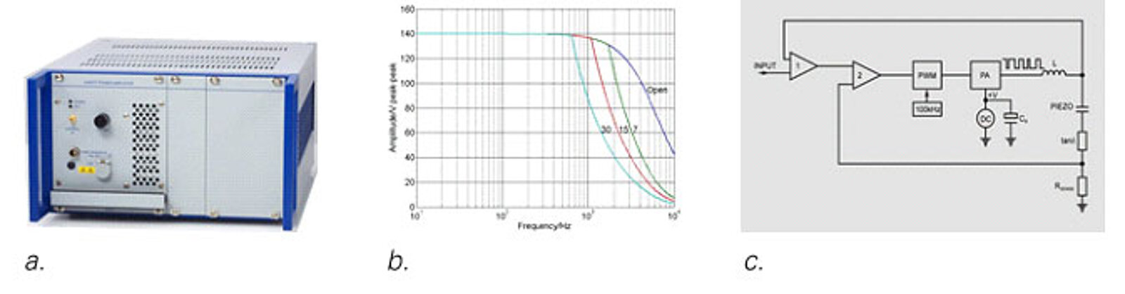
PI offers specific amplifiers for both applications (Fig. 7, Table 1). While the E-618 amplifier can provide very high peak currents for high repetition rate pulse applications, the E-617KDYN is designed for high frequency continuous operation. It is based on an energy recovery circuit. In this case, the reactive energy flowing back to the amplifier (Fig. 4b) is temporarily stored via a buffer capacitor. This means that up to 80% of the energy used during the previous charging process is available to be reused for the next charging process. This drive principle uses significantly less power than a conventional linear amplifier (see Table 1).
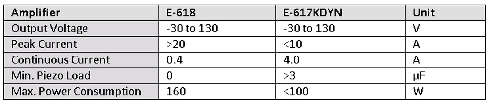
In addition, both amplifiers have an input for a PT1000 temperature sensor. If such an element is attached to the actuator (see section 2.3), the actuator temperature in the amplifier can be constantly monitored. When the temperature exceeds a defined limit value, the device switches off automatically.
3 Test Setup
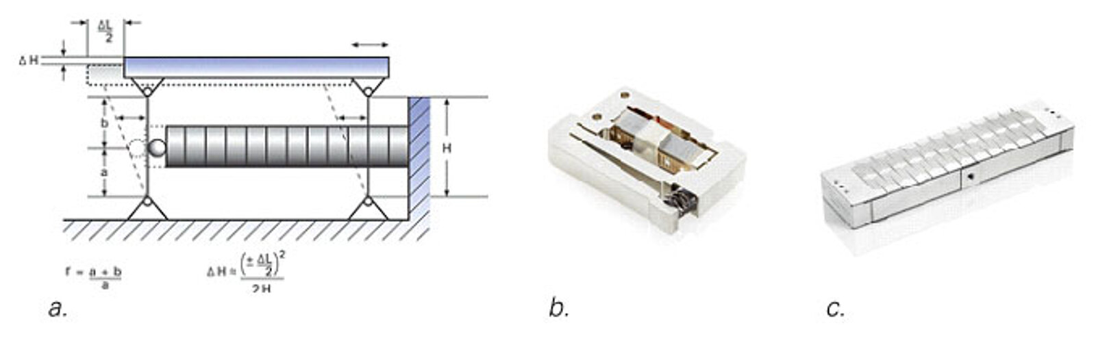
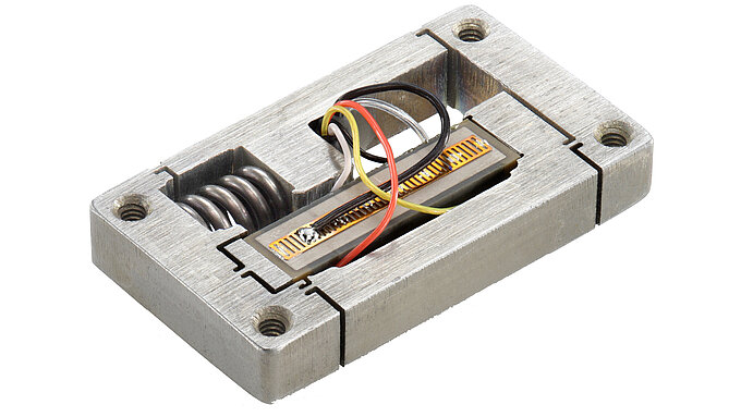
In order to investigate the dynamic properties, 5x5x36mm³ PICMA® actuators were inserted into a mechanical pretensioning frame (Fig. 8). Bare ceramic samples and encapsulated samples with internal heat conductive media (see section 2.3, Fig. 6) were installed. The mechanical pretension of 400N or 16MPa (relative to the actuator cross-section) is achieved by means of plate springs in the upper part of the frame. In order to ensure a homogeneous force distribution, ball-cone connections are installed above and below the actuator.
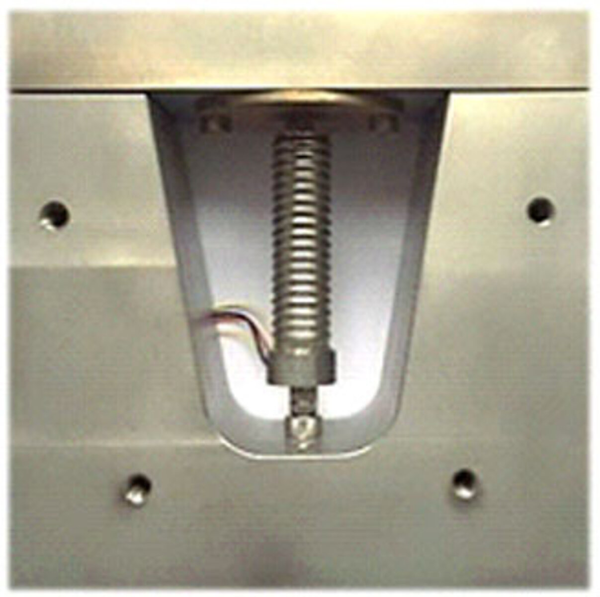
In order to test different cooling measures on the actuator, the side surfaces of the frame can be sealed with covers (see threaded holes in Fig. 8). Compressed air connections are mounted on the covers so that different cooling media can be directed past the actuator. Pressured air (22°C, 40m³/h flow rate) and water (15°C, 40l/h) were tested. The piezo actuators were driven by the above mentioned E-617 and E-618 amplifiers (see illustration in section 4), either with a sinusoidal signal or with a rectangular / trapezoidal signal with rise times of 60 μs (see illustration in section 4).
A PT1000 sensor attached directly to the piezo actuator surface was used to measure the actuator temperature (see section 2.3). During the tests, the frequency was gradually increased until a thermal steady state was reached (thermal time constant: ~5min in air, ~45sec in water). The process was continued until the specified limit temperature was reached (see graph in section 4).
4 Results
4.1 Non-Encapsulated PICMA® Stack Actuators
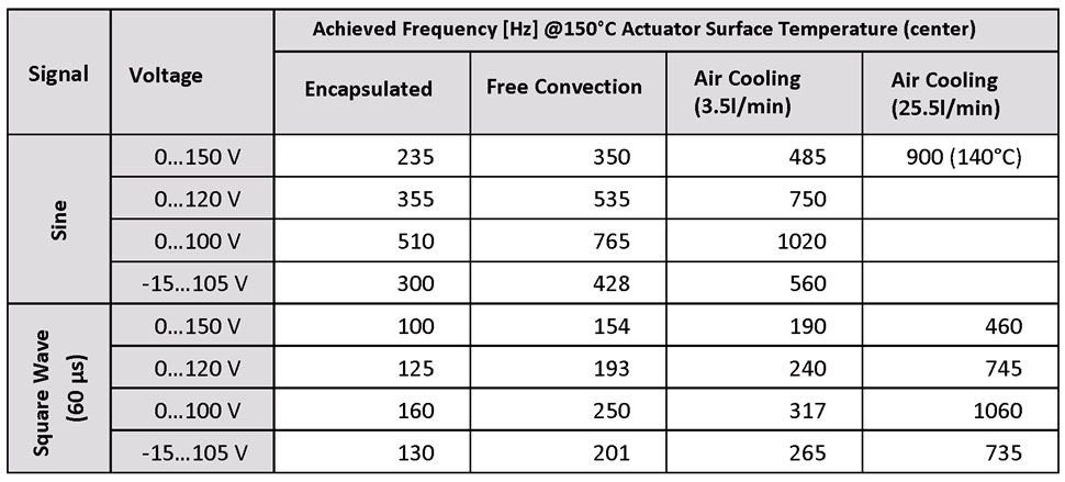
The effect of different cooling measures, control signal types, and drive voltage amplitudes was investigated on bare 5x5x36 mm³ PICMA® stack actuators (Fig. 1a). The control frequency was increased, step by step, in the conditions described in Table 2 until the limit temperature of 150°C was reached at the actuator surface. The condition “Free Convection” was measured as shown in Fig. 8 without the side covers. To simulate a housing (“Encapsulated”), the side covers were bolted on.
4.2 Hermetically Encapsulated PICMA® Stack Actuators
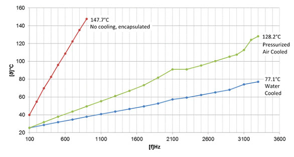
Figure 9 shows the results of the self-heating tests for different cooling measures conducted on 5x5x36mm³ encapsulated PICMA® stack actuators (see Fig. 6). The actuators were driven by a sinusoidal signal of 0 to 100V.
5 Flexure Actuators – Guidance and Motion Amplification
To make piezo actuators more robust and accessible for integration into real-world applications, stacks can be packaged inside a flexure arrangement, providing precision guidance and amplified motion along with a better mounting interface. Flexures are usually made of aluminum, steel or titanium. When designed properly, there is no friction and wear and they can provide billions of cycles of maintenance-free service.
6 Discussion
Comparing the results of non-encapsulated PICMA® stack actuators driven with a sine wave signal with those driven by a square wave signal (Table 2) shows that 2 to 3 times higher frequencies are achievable with sinusoidal operation. This is not surprising since the harmonic content in the square waves that contributes to the additional losses is missing from the pure sine wave operation. The strong dependence of the power loss on the drive voltage amplitude (~V²) can also be seen from the measured values in Table 2.
In addition, the different loss factors between pure unipolar control and semi-bipolar control is shown for identical amplitudes at 0V to 120 V and -15V to 105V. The closer the operation gets to the polarity reversal point, the more it effects the reorientations and dielectric hysteresis, increasing the effective loss factor (see Fig. 4b), and limiting the achievable frequency.
Air cooling allows 4-5 times higher frequencies compared to the confined condition without free convection. A further increase of nearly one order of magnitude is possible by liquid cooling of the encapsulated PICMA® actuators filled with heat conductive paste (Fig. 9). While air cooling allows frequencies up to 1kHz, 3.3kHz can be reached using liquid cooling. Even at amplitudes of 100Vpp (equivalent to 35μm displacement). the temperature only rises to 80°C maintaining a significant safety margin to the maximum allowable temperature of 150°C. The upper frequency limit in the experiment was determined by the bandwidth of the E-617KDYN amplifier (see Fig. 7b).
The high repetition frequencies allow very high cycle numbers to be reached within a short time interval. In life-time tests conducted on five samples of bare and encapsulated 5x5x36mm³ PICMA® stacks each, it was demonstrated that the actuators can run 1010 (10 billion) cycles without failures.
7 Summary
Tests conducted with encapsulated PICMA® stack actuators, filled with heat conductive paste, and operated with active liquid cooling demonstrated that continuous operation at full nominal displacement of 35µm is feasible with frequencies up to 3,300Hz, for sinusoidal drive signals. Higher frequencies could not be tested due to the power and bandwidth limitations of the E-617KDYN amplifier that was used in the experiments. For the best results in OEM applications, flexure piezo mechanisms, with integrated guidance, preloaded and motion amplifier, as well as position and temperature feedback, are recommended. The high performance of these readily available actuators can extend the limits of applications, such as high throughput micro dispensing, active vibration cancellation, and fast tool servos.
References
[1] HEYWANG, W., K. LUBITZ UND W. WERSING (Eds.): Piezoelectricity Evolution and Future of a Technology. Springer-Verlag Berlin/Heidelberg, 2008.
[2] JAFFE, B., W.R. COOK UND H.L. JAFFE: Piezoelectric ceramics. Academic Press, 1971.
[3] HOLTERMAN, J. UND W.A. GROEN: An introduction to piezoelectric materials and components. Stichting Applied Piezo, Appeldorn, the Netherlands, 2013.
[4] SIROHI, J. UND I. CHOPRA: Design and development of a high pumping frequency piezoelectric-hydraulic hybrid actua-tor. Journal of Intelligent Material Systems and Structures, Vol. 14, 2003, No.3, S. 135-147.
[5] PI Ceramic GmbH: Piezoelektrische Aktoren. Bauelemente – Technologie – Ansteuerung. Katalog 2013. Download at www.piceramic.com.
[6] PERTSCH, P., S. RICHTER, D. KOPSCH, N. KRÄMER, J. POGODZIK UND E. HENNIG: Reliability of piezoelectric multilayer actuators. Conference proceedings ACTUATOR 2006, Bremen 2006, S. 527-529.
[7] Physik Instrumente (PI) GmbH & Co. KG: Piezo Nano Positioning Product Catalog 2014/2015, download at www.pi.ws.
[8] SHERRIT, S., C. JONES, J. ALDRICH, C. BLODGET, X. BAO, M. BADESCU UND Y. BAR-COHEN: Characterization of piezoelec-tric stacks for space applications. Conference proceedings 11th Earth & Space Conference, Long Beach CA, 2008, S. 1-10.
[9] FOUAIDY, M., G. MARTINET, N. HAMMOUDI UND F. CHATELET: Full Characterization of Piezoelectric Actuators used for Superconducting RF Cavities Fast Active Tuning. CARE-Report-2007-015-SRF, EU Contract No. RII3-CT-2003-506395, 2007.
[10] PERTSCH, P.: Das Großsignalverhalten elektromechanischer Festkörperaktoren. ISLE-Verlag, Ilmenau, 2003.

Blog Categories
- Aero-Space
- Air Bearing Stages, Components, Systems
- Astronomy
- Automation, Nano-Automation
- Beamline Instrumentation
- Bio-Medical
- Hexapods
- Imaging & Microscopy
- Laser Machining, Processing
- Linear Actuators
- Linear Motor, Positioning System
- Metrology
- Microscopy
- Motorized Precision Positioners
- Multi-Axis Motion
- Nanopositioning
- Photonics
- Piezo Actuators, Motors
- Piezo Mechanics
- Piezo Transducers / Sensors
- Precision Machining
- Semicon
- Software Tools
- UHV Positioning Stage
- Voice Coil Linear Actuator
- X-Ray Spectroscopy