Piezo Motion Control Tutorial - Piezo Basics for Precision Motion, Force Generation & Nanopositioning Applications in Industry and Research
Why All Piezo Motors are NOT Created Equal
Why Use Piezo Motion?
Piezo motion is used when a combination of any of these parameters is required:
The demand for higher speed and/or precision in fields such as bio-nanotechnology, semiconductors, metrology, data comm, and photonics keep pushing manufacturers to come up with innovative drive technologies.
There is not one single type of piezo drive that works for every application. PI provides a large variety of piezo actuator and piezo motor drive technologies, each one optimized for different parameters such as cost, precision, force, speed and size. To use the advantages of piezoelectric positioning technology to its full extent, it is important to carefully analyze the application in which a piezo drive or nano-positioning system is to be used. Close contact between user and manufacturer is the best recipe for success.
This tutorial includes an introduction to the piezoelectric effect, a discussion of the difference bewtween a piezo actuator and a piezo motors, an explanation of hybrid mechanisms, and a quick start guide to PI piezo motion products. Email our engineers if you have additional questions about using PI piezo motion products to solve your application problem.

Piezo drives are vital in today's ultra-precision motion control systems. They provide the best combination of stability, accuracy, responsiveness and resolution.
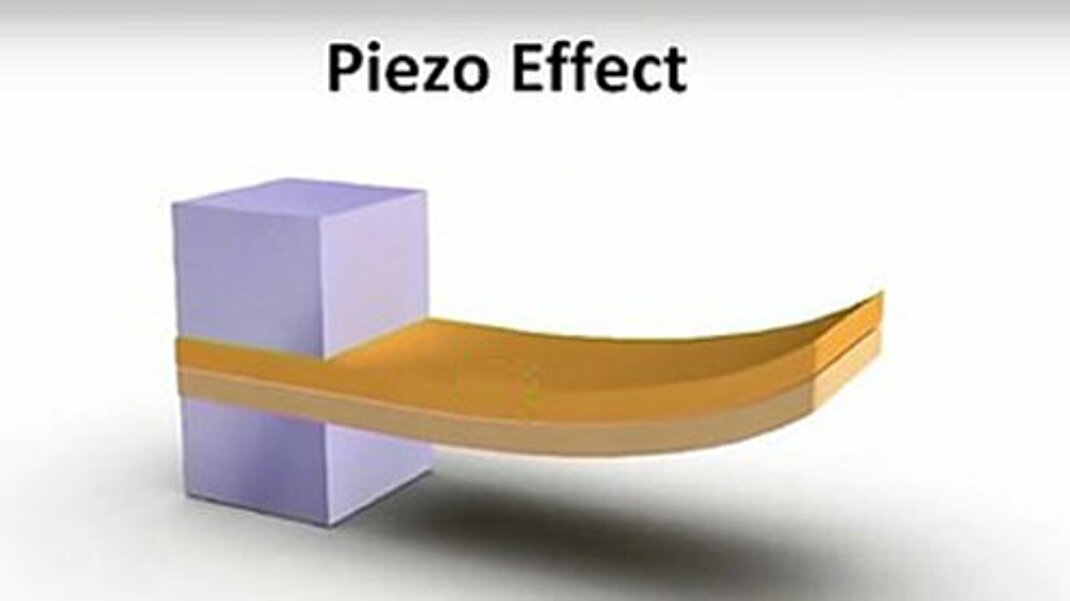
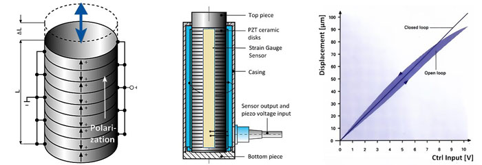
The piezoelectric effect – the conversion of electrical energy to mechanical energy and vice versa - is exhibited by natural materials, such as quartz, etc. However, man-made polycrystalline ferroelectric ceramic materials, such as Lead Zirconate Titanate (PZT), have far advanced material properties and achieve more gain. Ferroelectric ceramics need to be poled to become piezoelectric. Charge separation between the positive and negative ions is the reason for electric dipole behavior of the piezoelectric effect. Piezoelectric ceramics come in many variations optimized for actuator or sensor applications.
Origin of Piezo
The term “piezo” is derived from the Greek word for pressure. In 1880, Jacques and Pierre Curie discovered that an electric potential could be generated by applying pressure to quartz crystals; they named this phenomenon the “piezo effect”. Later, they ascertained that when exposed to an electric potential, piezoelectric materials change shape. This they named the “inverse piezo effect”.
More on the fundamentals of the piezo effect, equations and background information
Piezoelectric materials are used to convert electrical energy to mechanical energy, and vice-versa. The precise motion that results when an electric potential is applied to a piezoelectric material is of primordial importance for nanopositioning. Actuators using the piezo effect have been commercially available for 35 years and in that time have transformed the world of precision positioning and motion control.
Piezo ceramics needs to be polarized to show the piezo effect.
Open and Closed Loop Operation
In most applications, piezo positioners are used with a position feedback sensor and closed-loop control.
In contrast to many other types of drive systems, some piezo actuators can be operated without servo-control for a variety of applications. With suitable controllers, closed-loop operation enables reproducibilities in the sub-nanometer range as well as elimination of the piezo hysteresis. Learn more on digital vs. analog piezo controllers for closed-loop operation
PZT Ceramics Manufacturing Process
PI develops and manufactures its own piezo ceramic materials at its PI Ceramic factory. Multilayer and bulk piezo actuators use different manufacturing processes. Both require a number of highly specialized machines. More information on piezo manufacturing technologies at PI Ceramic.
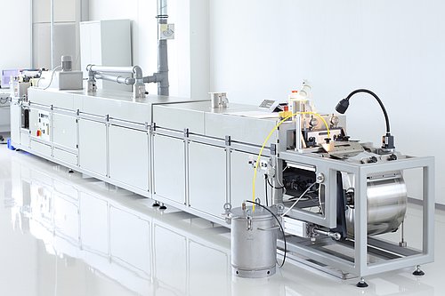
For a quick overview, click here
Piezo motion devices are often divided into two groups: actuators and motors.
Traditional piezo actuators expand analogous to the applied drive voltage. They provide short travel ranges typically under 1mm.
Piezoelectric motors require more complex drive electronics and can provide long travel ranges (up to 100’s of mm). They typically consist of one or more of piezo elements driving a runner.
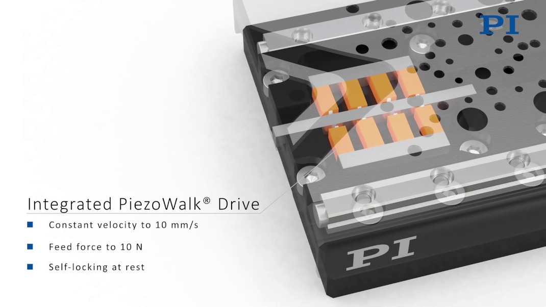
Piezo Motors are based on different drive principles optimized for high force, high speed, minimized dimensions and cost. All piezo motors are intrinsically non-magnetic, vacuum compatible and self-locking at rest.
Piezo Inertia motors (stick-slip) are most compact and simple with relatively low forces of 1N to 10N and speed to 10 mm/sec.
Ultrasonic resonant motors provide a wide dynamic range from microns/second and below to 100’s of mm/sec.
PiezoWalk® linear motors can achieve the highest forces along with picometer resolution, however velocity is limited from 1mm/sec for high force devices and up to 15mm/second for the new V-8 PicmaWalk drives.


Actuators are the most basic form of piezo drive elements and provide travel ranges from a few microns to a few 100 microns (1-2 mm in the case of bimorph or lever amplified actuators).
Actuators are divided into these basic groups:
- Piezo Stacks
- Highest stiffness & resonant frequency, travel typically 10 to 300 microns. Preloaded for push/pull.
- Programmable Piezo Shims
- Programmable shims are similar to piezo stack actuators but do not require a continuous voltage source to hold a position once programmed.
- Piezo Benders & Bimorphs
- Low profile, long travel to 2 mm, relatively low stiffness, and resonant frequency.
- Piezo Tubes
- Short travel (10 micron range) multi-axis motion feasible, often used as scanners in AFM.
- Piezo Shear Plates / Actuators
- Lateral motion, travel 10-20 microns, high stiffness, fast response.
Lifetime / Ceramic Encapsulation of Cofired Piezo Stacks

PI's piezo flexure nanopositioning systems employ the patented, award-winning PICMA® piezo actuators, the only polymer-free actuators with co-fired ceramic encapsulation. The monolithic PICMA® actuators are space qualified and were submitted to 100 billion cycles of life testing at NASA's JPL. Read about the testing
The PICMA piezo technology was specifically developed by PI’s piezoceramic division to provide higher performance and lifetime in nanopositioning applications. Cofired multilayer piezo actuators are similar to ceramic capacitors and are not affected by wear and tear. PI nanopositioning systems are designed to be driven at lower voltages than most other piezo systems (100 V vs. 150 V). The research literature, PI’s own test data, and 30+ years of experience all confirm that lower average electric fields lead to longer lifetime.
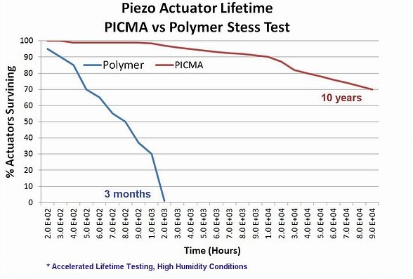
In addition, PI’s monolithic ceramic-encapsulated design provides better humidity protection than conventional polymer-film insulation. Diffusion of water molecules into the insulation layer is greatly reduced by the use of co-fired, outer ceramic encapsulation. Humidity is the main influence on the longterm reliability in low-dynamics or quasi-static operation modes, where the piezo actuator is supplied with a DC voltage to maintain a position for a long time.
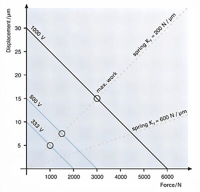
Force Generation: High Speed Valves, Dispensers, Pumps
One of the advantages of piezo ceramics is their high force generation and extremely fast response capabilities. This is why piezo actuators (mostly stacks and flexure amplified stacks) are often used to replace solenoids or other classical actuators in fast valve applications, micro-dispensers or pumps. It is helpful to understand how displacement and force correlate to get the most work out of an actuator. Internal and external spring constants should be similar. FEA simulations help optimize dynamics.
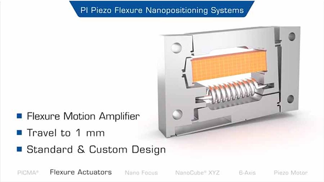
Guided piezo actuators (1 to 6 axes) are complex nanopositioners with integrated piezo drives and solid-state, friction-free linkages (flexures). They are used when requirements like the following need be met:
- Extremely straight and flat motion, or multi-axis motion with accuracy requirements in the sub-nanometer or sub-microradian range
- Isolation of the actuator from external forces and torques, protection from humidity and foreign particles
With the use of flexure guides and mechanical levers, the motion of a piezo stack can be multiplied (up to 100’s of microns or even a few mm) and guided at the same time. Flexure motion is based on the elastic deformation (flexing) of a solid material. Friction and stiction are entirely eliminated, and flexures exhibit high stiffness, load capacity, and resistance to shock and vibration. Flexures are maintenance free and not subject to wear. They are vacuum compatible, operate over a wide temperature range, and require neither lubricants nor compressed air for operation.

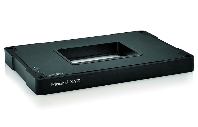
Piezo Stages: Positioners with Nanometer Class Guiding Precision and High Dynamics
PI piezo flexure nanopositioning and scanning stages provide frictionless flexure guidance with smoother and significantly straighter motion compared to conventional guiding systems (crossed roller bearings, etc.). The achievable resolution, reproducibility, straightness and flatness can only be matched by air bearing systems. PI piezo-driven flexure nanopositioners can easily achieve repeatability and minimum incremental motion in the subnanometer realm, which is measured and documented in our nano-metrology labs.

There are two ways to achieve multi-axis motion: parallel and serial kinematics. Serial kinematics (nested or stacked systems) are simpler and less costly to implement, but they have some limitations compared to parallel kinematics systems.
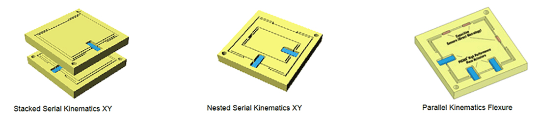

Serial Kinematics for Lower Cost / Standard Applications
In a multi-axis serial kinematics system, each actuator (and usually each sensor) is assigned to exactly one degree of freedom. Serial kinematic designs have advantages when it comes to cost and simplicity, and work very well for most standard applications.
Crosstalk
However, the manufacturing precision of even the best machines (and technicians) does not allow for crosstalk-free mechanics at the nanometer level, even in quasistatic operation. For many applications this is not an issue. In a parallel kinematics multi-axis system, all actuators drive only one moving platform, enabling reduced size and inertia, and the elimination of microfriction caused by moving cables. This way, the same resonant frequency and symmetrical dynamic behavior can be obtained for both the X and Y axes. The advantages are higher dynamics and scanning rates, better trajectory guidance, as well as better reproducibility and stability. Still, without the proper test metrology / instrumentation these advantages can easily be overlooked, and a serial kinematics system may appear to the best solution and the conclusion that there is no cross talk could be drawn (see also Coupled and Uncoupled Motion... below).
For the ultimate in dynamics straightness/flatness/orthogonality and for coordinate transformation situations (such as rotating about an arbitrary point in space), parallel kinematics are required. Parallel kinematics systems, if designed well, are superior to serial kinematics systems. To reap the benefits of parallel kinematics, you must have high-bandwidth, direct drivetrain-output metrology, so the workpiece can be simultaneously observed and controlled in multiple degrees of freedom.
Since it takes more experience and more advanced controllers to produce a good parallel kinematics precision positioning system, some designers try to avoid that challenge dismissing the technology as unpredictable, uncontrollable. Everyone who has seen a modern hexapod 6-axis motion system compared to a classical stack of translation and rotation stages will immediately understand the benefits of parallel kinematics.
Coupled and Uncoupled Motion, Static and Dynamic
Serial kinematics are sometimes referred to as uncoupled motion systems vs. coupled motion systems for parallel kinematics. When it comes the nanometer realm, uncoupled motion does not exist. By nesting or stacking a second and/or third axis onto a translation stage, there will be an influence on the first axis. Any load attached will have a further influence on all axes, even when at rest. And in positioning, things are not always at rest; actually most nanopositioning / scanning applications require very high dynamics. The seemingly uncoupled multiaxis-system then provides coupled (unwanted) motion in many degrees of freedom that cannot be detected by its internal serial metrology sensors, and hence goes partially uncontrolled. These errors may not be critical in many applications, but can be detrimental in some others.
Multi-Axis Measurements Relative to a Fixed Reference
Parallel kinematics facilitates implementation of Direct Parallel Metrology — measurement of all controlled degrees of freedom relative to ground. This is a more difficult design to build but it leads to clear performance advantages.
The parallel-kinematics / parallel metrology system “sees" motion in all controlled degrees of freedom and will respond to it. This means that all motion is inside the servo-loop, no matter which actuator (or unwanted external force / crosstalk) may have caused it, resulting in superior multi-axis precision, repeatability, and flatness. Direct parallel metrology also allows stiffer servo settings for faster response. Off-axis disturbances—external or internal, such as induced vibration caused by a fast step of one axis—can be damped by the servo.
High accuracy position feedback is essential in a good nanopositioning system, and direct motion metrology is the preferred choice. Direct metrology measures motion where it matters most to the application. Examples of high-resolution, direct metrology sensors are capacitive sensors, laser interferometers, and non-contact optical, incremental encoders. PI employs these and other sensors depending on the application requirements.
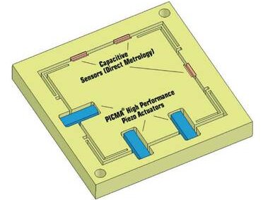
Capacitive Sensors
For travel ranges of less than 1mm, capacitive sensors have emerged as the default choice. They are compact, high-bandwidth and absolute measuring devices providing sub-nanometer resolution. For less demanding applications, strain gauge sensors (piezoresistive sensors) are a good alternative.
Capacitive sensors are high-value sensors composed of diamond-machined plates which directly measure the absolute position of the stage platform. Two-plate capacitive sensors consist of two RF-excited plates that are part of a capacitive bridge. One plate is fixed, the other plate is connected to the object to be positioned (e.g., the platform of a stage). The distance between the plates is inversely proportional to the capacitance, from which the displacement is calculated. Short-range, two-plate sensors can achieve resolution on the order of picometers. Residual tip/tilt errors are greatly reduced by PI’s ILS linearization system.
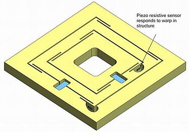
Piezoresistive (Semiconductor) Strain Gauge Sensors
Piezoresistive strain gauge sensors (PRS) are low-cost, high-resolution, but temperature-sensitive devices that are easily integrated in positioning devices. Like most strain gauge sensors, they are glued to the flexure structure or piezo stack, but the extra layer of epoxy between the sensor and structure makes it a challenge to get sufficient long-term stability. PRS do not measure distance directly, but infer position of the moving platform from the nanoscale warping of the structure. Due to the indirect measure of position, inaccuracies can occur and orthogonality errors are unobservable. Calibration to an interferometer allows them to achieve adequate accuracies for classical microscopy applications. Since their output signal is a low voltage DC current, the derived position can be more susceptible to noise pickup and drift.
Classical Film Strain Gauge Sensors
Film strain gauge sensors are another implementation of inferred metrology and are typically chosen for cost-sensitive applications. An SGS sensor consists of a resistive film bonded to the piezo stack or a guidance element; the film resistance changes when strain occurs. Up to four strain gauges (the actual configuration varies with the actuator construction) form a Wheatstone bridge driven by a DC voltage (5 to 10 V). When the bridge resistance changes, the sensor electronics converts the resulting voltage change into a signal proportional to the displacement.
Laser Interferometers
Laser interferometers are capable of accurately measuring long distances and some provide sub-nanometer resolution, although bulky optics must be mounted onto the moving elements of the motion system. PI uses interferometers in testing, calibrating, and qualifying nanopositioning systems.
Optical Encoders
Optical encoders are more compact and rely on diffraction between a moving reticle and a scale composed of finely pitched lines. Position is determined by counting fringes and interpolating between individual peaks, similar to interferometry. The latest linear encoders can provide resolution in the 100 picometer range and below.
Interferometers and incremental optical encoders are relative position sensors that must be initialized at a reference position. The stability of this reference position also influences the overall precision. While not yet common, high resolution absolute encoders break the nanometer barrier, but are still held back by high cost and more complex interfacing.
Choice of Control Interface: Digital or Analog or Both?
Analog interfacing provides high bandwidth and remains a popular way of commanding piezoelectric motion systems. It is usually the choice when the control signal in the application is provided in analog form. A key advantage of analog interfacing is its intrinsic deterministic (real-time) behavior, contrasted to the difficulty of accurately timing high-bandwidth communications on present-day multitasking PCs.
However, when analog control signals are not available, or when a significant distance between the control signal source and the nanopositioning controller would affect signal quality, digital interfacing (which must not be confused with digital control) is the preferred choice.

Digital signals can be transferred through copper wires, or for complete EMI immunity, through optical fibers.
Several types of digital interfaces are typically used in piezo-nanopositioning applications: TCP/IP, parallel-port, USB, SPI, RS-232, Fiber Link, GPIB, and, with some digital controllers, direct DSP links. For dynamic, high-precision applications, the exact timing of an interface can be significantly more important than the data transfer rate.
Interface Speed: Bandwidth vs. Timing and Determinacy. When Does It Matter?
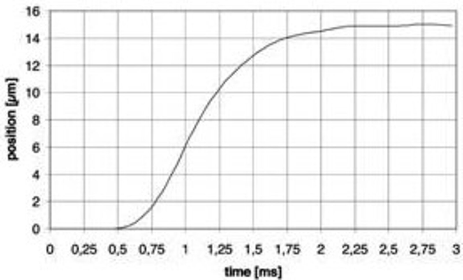
Piezo-driven stages can respond to a motion command on a millisecond or microsecond time scale.
That is why synchronization of motion commands and data acquisition have a high impact on the quality of many applications, like imaging or micromachining. Often it is not about interfacing speed, but determinacy; USB and TCP/IP are indeterminate, even though they are good at transmitting huge amounts of data. USB was designed to transfer large blocks of data at high speeds, but exact timing was not a big concern. While insignificant in less responsive positioning systems, this kind of nondeterministic behavior may not be tolerable in high-speed tracking or scanning applications. Each motion command—comprising just a few bytes—must be transferred instantaneously and without latency. A lowerbandwidth bus with higher timing accuracy may perform better in many applications. There are several factors that affect the response of a digital interface:
- the timing accuracy of the operating system on the controlling computer
- the bus timing protocol
- the bandwidth of the bus
- the time it takes the digital interface (in the piezo controller) to process each command
Parallel-port interfaces do not require command parsing and offer the best combination of throughput and timing accuracy.
In addition to the interface properties, the bandwidth of the nanopositioning system (mechanics and servo) matters. A slow system (e.g., 100 Hz resonant frequency) will not benefit from a responsive interface as much as a high-speed mechanism.
Modern closed-loop piezo motors are always operated with digital servo controllers. For piezo actuators and flexure positioners (where the displacement is proportional to the drive voltage) digital and analog servos are available.
The difference between a digital and analog piezo controller has nothing to do with the control interface. Analog controllers with digital interfaces are available as well as digital controllers with analog control interfaces. The answer lies in the servo part of the controller. Traditionally, piezo controllers were based on analog servos, due to the analog output nature of the position sensors employed. Digital servos permit the use of advanced control algorithms, error correction, and linearization schemes not feasible with analog servos. Learn more on digital and analog servo controllers

In addition, parameters can be changed on the fly, and optimization or adaptation to different load and operating conditions can be performed remotely without touching the controller hardware. There are other advantages, such as stage / controller interchangeability, etc.
However, all digital controllers are not the same. Poor implementations can add noise and lack certain capabilities of a well-designed analog implementation, such as fast settling time, compatibility with advanced feed-forward techniques, stability, and robust operation.
PI offers both analog and digital servo controllers. Overview here
All PI nanopositioning controllers (analog and digital) are equipped with one or more user-tunable notch filters. A controller with notch filter can be tuned to provide higher bandwidth because side-effects of system resonances can be suppressed before they affect system stability.
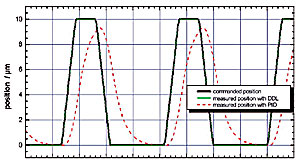
Conventional piezo controllers cannot completely eliminate phaseshift and tracking errors in applications with rapid, periodic motion. This is due in part to the non-linear nature of the piezoelectric material, the finite control bandwidth, and the inherent limitations of P-I-D (proportional integral derivative) servo-control, which cannot react before a position error is detected.
The DDL firmware upgrade option, available with most digital piezo controllers, solves this problem. This technology, developed by PI, reduces the error between the current and desired position to imperceptible values. The dynamic linearity and effectively usable bandwidth are thus improved by up to three orders of magnitude (1000-fold). DDL is of benefit to single- and multi-axis applications where motion follows a given trajectory repeatedly.
APC vs. PID Servo Control Algorithm
An alternative control concept to PID is available for the modular E-712 controller for nanopositioning systems: Advanced Piezo Control. It is based on a state controller which, in turn, is based on a model of the positioning system. Advanced Piezo Control actively damps the resonance frequency, in contrast to conventional PID controllers with notch filter where the mechanical resonance is cut out of the excitation spectrum.
Advanced Piezo Control provides faster settling times and lower sensitivity with respect to interferences from the outside. The phase trueness is significantly improved compared to the damping with one or even two notch filters. This has immediate effects on the trajectory trueness and the settling response.
Limitations: If the mechanical system has too many resonances close together, or if the resonance frequency to be damped is about 1 kHz or more, the state controller in this form no longer has any advantage over conventional PID controllers. Learn more on advanced control algorithms
Power Requirements for Linear Amplifiers / Piezo Actuator Operation
The operating limits of a linear piezo amplifier depend on the amplifier power, the amplifier design, and last but not least, the electrical capacitance of the piezo mechanism. For dynamic applications, piezo mechanisms require high charge and discharge currents. Those requirements are best met by power amplifiers that can source and sink high peak currents. The average current is usually of secondary importance. For exact information on maximum operating frequency with a given piezo load refer to the individual operating limits graphs in the PI product spec sheets.
Open-loop operating limits data for PI piezo power amplifiers are tested 15 minutes of continuous operation at room temperature. At power up, (cold conditions) the maximum operating frequency can be higher.
The indicated capacitance values for piezo actuators and mechanisms in PI datasheets are small-signal values (measured at 1 V, 1000 Hz, 20 °C, no load). The capacitance of piezo ceramics changes significantly with amplitude, temperature, and load, up to approximately 200% of the unloaded small-signal capacitance at room temperature. Therefore, the operating limits graphs actually reflect a significantly higher load to the amplifier compared to what a standard capacitor of the same value would represent.
More information is available in the tutorial on the PI Ceramic website
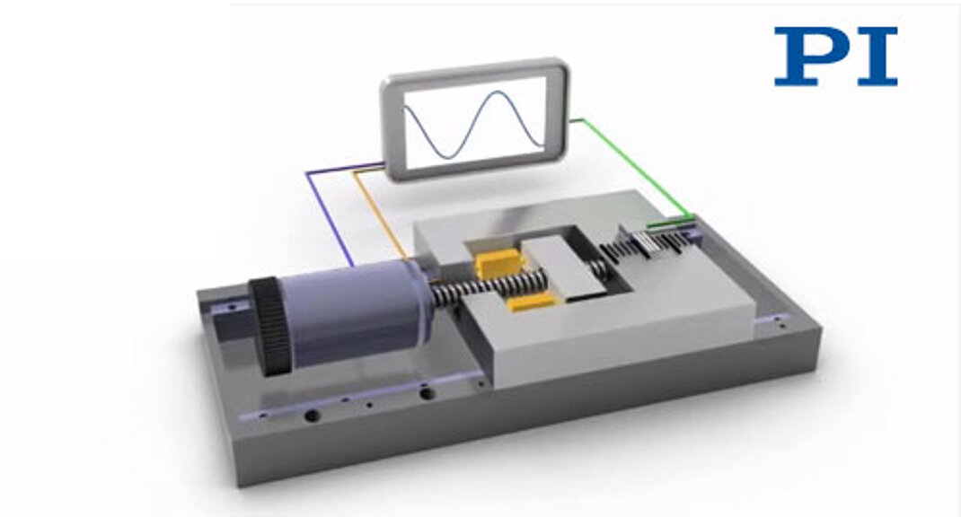
Hybrid actuation - based on a combination of piezo (or voice coil) and ballscrew drives - overcomes the limitations of the individual technologies. The result is ultra-smooth, high resolution motion, with tracking accuracy to 1nm.
Piezo actuation can also be used to enhance the performance of classical motors and drive systems, forming a coarse/fine positioning system. Traditional coarse/fine mechanisms were run with independent control loops, hindering overall system repeatability and accuracy. The advent of higher-performance motion-control chips and linear encoders with nanometer-scale resolution has allowed construction of hybrid mechanisms in which one feedback sensor provides information to both the coarse- and fine-control loops.
The construction of such a hybrid servo is significantly more complex (analogous to controlling an internal combustion engine and electric motor in a hybrid vehicle at the same time) and the result is the combination of piezo-class dynamics, repeatability, and high stiffness with many centimeters of travel. Requirements for motion devices like these come from the astronomy community, where the next generation of multimirror optical telescopes need long travel, extremely high forces, and motion uniformity with tracking accuracy of less than 2 nm and short-term interpolation errors of less than 0.5 nm.
Piezo motors are used where long travel ranges in the millimeter to 100’s of mm range are required. Piezo motors can be divided into three main categories:
- Resonant Motors (Ultrasonic Motors)
- High speed, compact, quiet
- Piezo-Walk Motors (Stepping Motors)
- High force, more complex, very high resolution and stability, low speed
- Inertia Motors (Stick-Slip Motors)
- Most compact, lowest cost
A great advantage of piezo motors is their intrinsic steady-state auto-locking capability. It does away with servo dither and the accompanying heat generation, an undesirable feature of electromagnetic linear motors. Stepping and resonant (continuous) piezo motors are in principle nonmagnetic and vacuum-compatible, a requirement for many applications in the semiconductor optics and medical industry.
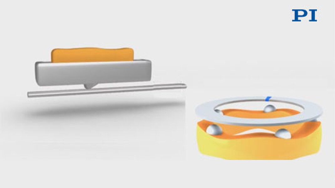
The motion of resonant piezo motors is based on high frequency oscillation with microscopic amplitudes. The oscillatory motion of the piezo ceramic block is transmitted to a ceramic runner (linear or circular) coupled to a moving stage. Ultrasonic motors are very compact and can attain high speeds combined with resolutions down to a few nanometers or better. Rotary motors feature high torques, especially at low rpm.
By eliminating lead-screws and their inertia and associated linkages and structures, such mechanisms can be significantly smaller and more responsive than classical motor drives. For example, off-the-shelf linear stages can provide 20mm of travel at up to 100’s of mm/s speed, 10g acceleration with a 0.1 mm resolution linear encoder, all in a package 35mm square.
In-position stability is superior to conventional stages since the actuator acts as a brake when quiescent. Fieldlessness, vacuum-compatibility, long life, and other signature advantages of piezo actuation also apply.
The drawback to these piezomotors has traditionally been their difficulty of control. These problems were solved with the latest generation of ultrasonic motor controllers developed by PI. An autotuning circuit constantly keeps the oscillator frequency in the optimum range; and a fast processor now automatically switches between gainsets, enabling the user to take full advantage of excellent velocity constancy, wide dynamic range, and the exceptional stability these friction motors provide at rest.
Tech Articles & Apps:
Positioning Performance of Ultrasonic Motors
Reliability of Ultrasonic Motors
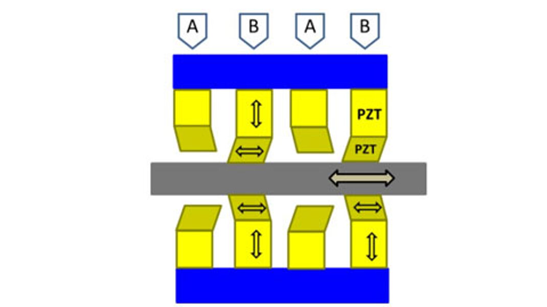
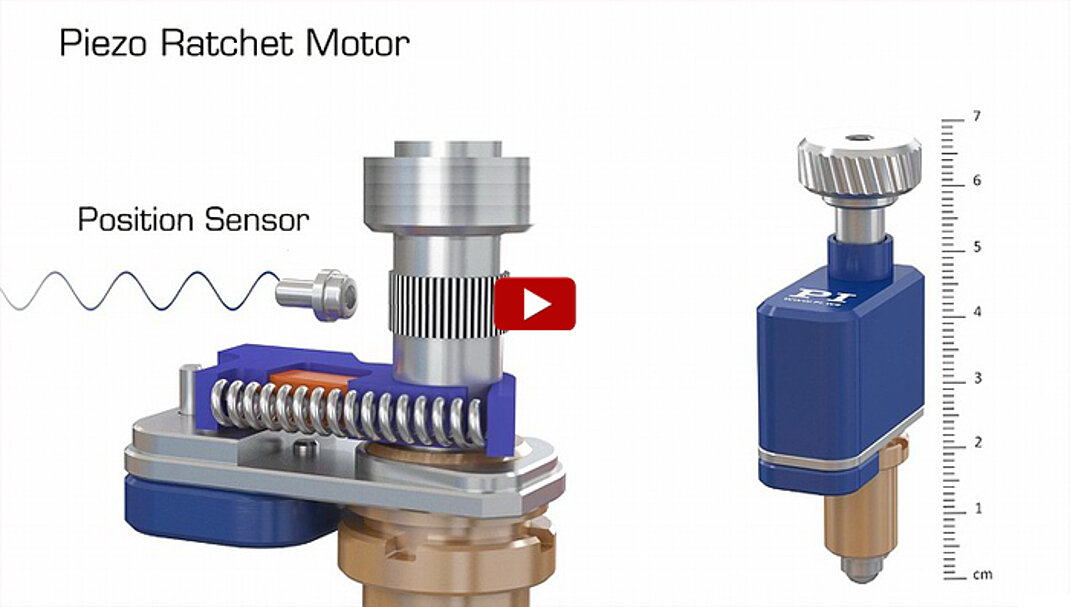
By combining piezo elements acting in longitudinal and transverse directions, the foundation for a walking actuator is composed. These elements can be compressed against a longitudinal rod to confer motion. One familiar progenitor of this family of mechanisms was the Burleigh Inchworm. More recently-developed mechanisms offer extraordinary stiffness and holding force and are optimized for reliability in applications requiring long-term position hold while providing centimeters of travel with picometer-class resolution.
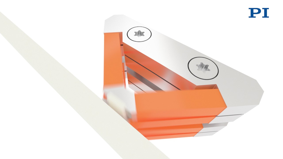
An even newer solution uses cost-effective bender-type piezo elements. Size and cost are substantially reduced; speed is increased by a factor of 10 while power-off stiffness is still remarkable, with 10N holding force. This design also provides centimeters of travel range and picometer-class resolution, ideal for applications like optic positioning in microlithography and sample positioning in electron microscopy.
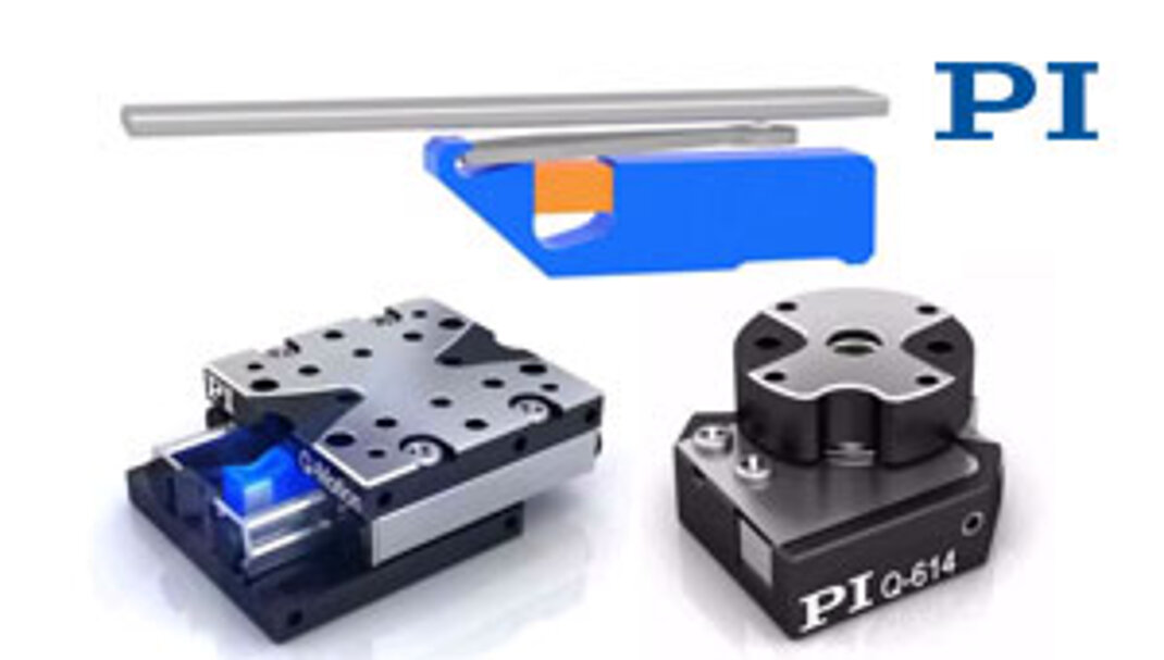
These compact motors are based on the stick-slip effect (analogous to the tablecloth trick), a cyclical alternation of static and sliding friction between a moving runner and the drive element. PI provides linear and rotary stick-slip motors. Like the other types of piezo motors described above, they provide high resolution and excellent long term stability with self-locking capabilities.
Energy-saving, Low Cost Drive Electronics
These motors are used when cost and compact dimensions are a major concern. PI offers several low-cost positioners based on piezo inertia drives with relatively high holding forces of up to 10 N, velocities of more than 5 mm/s and a travel range that is only limited by the length of the moving carriage or runner. The driving element is a miniature multilayer low-voltage piezo stack.
Several drive-modes are available, some operating at a frequency beyond what the human ear can pick up. At a standstill, the drive produces its maximum clamping force, with zero holding current and no heat generation. Because of the relatively simple drive concept, drive electronics can be designed compact and cost efficient, many piezo motor types can run on 48 V or less.

Basic Piezo Actuators (PZT Stacks, Tubes, Shear-Actuator, Benders)
These actuators expand /contract proportionally to the applied drive voltage. Displacement is typically 10 to 100s of microns, up to a few mm for benders. Usually, there is a tradeoff between force and displacement.
Features
- High to very high forces up to 50,000 N
- Very fast response – microsecond to millisecond range
- No wear and tear, no friction, sub-nanometer resolution feasible
- 100 billion cycles life tested for the MARS mission
- Travel range typically 10 to 200 µm (stacks); few mm for bimorph and benders
- Closed-loop operation with feedback sensor for higher linearity
Sub-Groups
Stacked Actuators
- Cofired multilayer construction (low voltage) and classical design (stack of discrete PZT disks/electrodes). High force, motion typically up to 200 µm. Also available with aperture.
Shear Actuators
- Lateral motion allows design of small, very fast XY and XYZ positioners, also used in piezo stepping motor designs. High force, travel typically limited to 20 µm.
Tube Actuators
- Often used as scanner tubes for AFM microscopy and for microdispensing (pump) applications. Very fast response (low inertia), low force (fragile), travel range typically <20 µm. XY scanner tubes available.
Bender Actuators
- Available in multilayer construction (60 V); and classical (bimorph) design (200 to 1,000 V). Low force (< 10 N), very long deflection (to several millimeters), medium response (approximately 10 msec).

Flexure Guided Actuators / Positioning Stages (1-6 Axes)
Flexure-guided, piezo stack-driven nanopositioning and scanning stages or actuators are available. These devices use frictionless flexures and motion amplifiers to provide extremely straight and flat motion, along with longer displacement than can be accomplished with simple piezo actuators. For the highest accuracy, integrated capacitive position sensors provide sub-nanometer precision in multiple degrees of freedom.
Features
- Frictionless, fast response (0.1 to 10 ms), nanometer to sub-nanometer resolution, high scanning frequencies to kilohertz range
- Integrated multiaxis-positioning stages available
- Internal motion amplifiers provide motion range up to 2,000 µm
- Essential for nanoalignment, imaging, scanning and nanomanipulation
- Position feedback sensor can be integrated (typically strain gauges for entry level, or capacitive for high-end systems and independent multi-axis measurements)
For both basic and flexure guided actuators, displacement is proportional to the DC output voltage of the piezo driver/servo controller. A position feedback sensor is required for linearization, due to the nonlinear behavior of piezo material. If linearity is not critical, open loop application is also possible.

Piezo motors use different types of controllers, and typically, incremental feedback sensors. Force and displacement are not interdependent.
Features
- Based on high frequency oscillation of a piezo plate (stator) at the nanoscale
- Oscillation is transferred to a slide or rotor via micro-friction
- Unlimited motion range, high speed (to 1000 mm/s in some of the latest designs), fast response (10 to 10s of ms)
- Resolution typically 10 to 50 nanometers, forces, typically 2 to 10 N
- Power-off, position-hold capability (self clamping)
- Small amount of particle generation due to friction

Features
- Virtually unlimited motion range
- Based on accumulation of small highly controllable steps
- Picometer resolution by means of direct piezo actuation (linear mode, dither mode)
- High forces to 800 N
- Speed 1 to 10 mm/s
- Fast response (< 1 m/sec feasible)
- Very high stiffness
- Drift-free position-hold when powered down