


Piezo Effect Basics
The piezoelectric effect is often encountered in daily life. For example, in small butane cigarette or gas grill lighters, a lever applies pressure to a piezoelectric crystal creating an electric field strong enough to produce a spark to ignite the gas. Furthermore, alarm clocks often use a piezoelectric element. When AC voltage is applied, the piezoelectric material moves at the frequency of the applied voltage and the resulting sound is loud enough to wake even the strongest sleeper. For more detailed information see Fundamentals of Piezoelectricity and Piezo Actuators.
The word "piezo" is derived from the Greek word for pressure. In 1880, Jacques and Pierre Curie discovered that pressure applied to a quartz crystal creates an electrical charge in the crystal; they called this phenomena the piezo effect. Later they also verified that an electrical field applied to the crystal would lead to a deformation of the material. This effect is referred to as the inverse piezo effect. After the discovery it took several decades to utilize the piezoelectric phenomenon. The first commercial applications were ultrasonic submarine detectors developed during World War I and in the 1940’s scientists discovered that barium titanate ceramics could be made piezoelectric in an electric field.

As stated above, piezoelectric materials can be used to convert electrical energy into mechanical energy and vice versa. For nanopositioning, the precise motion which results when an electric field is applied to a piezoelectric material is of great value. Actuators using this effect first became available around 20 years ago and have changed the world of precision positioning.
Piezoelectric actuators (PZTs) offer the user several benefits and advantages over other motion techniques:
- Repeatable nanometer and sub-nanometer sized steps at high frequency can be achieved with Piezo devices because they derive their motion through solid state crystal effects. There are no moving parts (no "stick-slip" effect).
- Piezo devices can be designed to move heavy loads (several tons) or can be made to move lighter loads at frequencies of several 10 kHz.
- Piezo devices act as capacitive loads and require very little power in static operation, simplifying power supply needs.
- Piezo motion devices require no maintenance because they are solid state and their motion is based on molecular effects within the ferroelectric crystals
With high-reliability Piezo materials a strain on the order of 1/1000 (0.1%) can be achieved; this means that a 100 mm long Piezo actuator can expand by 100 micrometers when the maximum allowable field is applied.
More: Piezo Motion Tutorial
Low Voltage and High Voltage Piezo Elements (PZTs)
Two main types of piezo actuators are available: low voltage (multilayer) devices requiring about 100 volts for full motion and high voltage devices requiring about 1000 volts for full extension. Modern piezo ceramics capable of greater motion replace the natural material used by the Curies, in both types of devices. Lead zirconate titanate (Piezo) based ceramic materials are most often used today. Actuators made of this ceramic are often referred to as Piezo actuators.
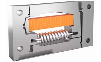
The maximum electrical field Piezo ceramics can withstand is on the order of 1 to 2 kV/mm. In order to keep the operating voltage within practical limits, Piezo actuators consist of thin layers of electroactive ceramic material electrically connected in parallel. The net positive displacement is the sum of the strain of the individual layers. The thickness of the individual layer determines the maximum operating voltage for the piezo actuator.
High voltage piezo actuators are constructed from 0.5 to 1.0 mm layers while low voltage multilayer piezo actuators are monolithic (diffusion bonded) multilayer designs constructed from 20 to 100 µm layers.
Both types of piezo actuators can be used for many applications: Low voltage actuators facilitate drive electronics design, high voltage types operate to higher temperatures (150 °C compared to 80 °C). Due to manufacturing technology high voltage ceramics can be designed with larger cross-sections for higher load applications (up to several tons) than low voltage ceramics.

Resolution not Limited by Friction
Resolution not Limited by Friction
Piezo actuators have no "stick slip" effect and therefore offer theoretically unlimited resolution. This feature is important since PZTs used in atomic force microscopes are often required to move distances less than one atomic diameter. In practice, actual resolution can be limited by a number of factors such as piezo amplifier (electric noise results in unwanted displacement), sensor & control electronics (noise and sensitivity to EMI affect the positional resolution and stability) and mechanical parameters (design and mounting precision of the sensor, actuator and preload influence micro-friction which limits resolution and accuracy). PI Closed Loop Piezo Actuators provide sub-nanometer resolution and stability.
Closed Loop and Open Loop Piezo Device Operation
Piezo actuators can be operated in open and closed loop. In open loop, displacement roughly corresponds to the drive voltage. This mode is ideal when the absolute position accuracy is not critical or when the position is controlled by data provided by an external sensor (interferometer, CCD chip etc.). Open loop piezo actuators exhibit hysteresis and creep behavior (like other open loop positioning systems).
Closed loop actuators are ideal for applications requiring high linearity, long-term position stability, repeatability and accuracy. PI Closed Loop Piezo Actuators & Systems are equipped with position measuring systems providing sub-nanometer resolution and bandwidth up to 10 kHz. A servo controller (digital or analog) determines the output voltage to the Piezo by comparing a reference signal (commanded position) to the actual sensor fed back position signal.
PI has designed multi-axis Closed Loop Piezo positioners that offer the possibility of repeatedly locating a point within a 1 x 1 x 1 nanometer cube. It is important to remember that such accuracy is obtainable only if the surrounding environment is controlled, since temperature changes and vibrations will cause changes in position at the nanometer level.
Dynamic Behavior
A piezo actuator can reach its nominal displacement in approximately 1/3 of the period of the resonant frequency. Rise times on the order of microseconds and accelerations of more than 10,000 g's are possible. This feature permits rapid switching applications. Injector nozzle valves, hydraulic valves, electrical relays, adaptive optics and optical switches are a few examples of fast-switching applications.
Resonant frequencies of industrial reliability piezo actuators range from a few tens of kHz for actuators with total travel of a few microns to a few kHz for actuators with travel more than 100 microns. These figures are valid for the piezo itself; an additional load will decrease the resonant frequency as a function of the square root of the mass (quadrupling the mass will halve the resonant frequency).
Piezo actuators are not designed to be driven at resonant frequency (with full stroke and load), as the resulting high dynamic forces might endanger the structural integrity of the ceramic material.

Mechanical Considerations for Piezo Operation
Mechanical Stiffness
In a first approximation, a piezo actuator can be regarded as a spring/mass system. The stiffness or spring constant of a piezo actuator depends on the Young's Modulus of the ceramic (approximately 25 % that of steel), the cross section and length of the active material (and a number of other parameters).
Load Capacity and Force Generation for Piezo Motion Devices
Piezo ceramics can withstand high pushing forces and carry loads to several tons. Even when fully loaded, the Piezo will not lose any travel as long as the maximum load capacity is not exceeded.
Load capacity and force generation must be distinguished. The maximum force (blocked force) a piezo can generate is determined by the product of the stiffness and the total travel. A piezo actuator (as most other actuators) pushing against a spring load will not reach its nominal displacement. The reduction in displacement is dependent on the ratio of the piezo stiffness to the spring stiffness. As the spring stiffness increases, the displacement decreases and the generated force increases (for more information click here).
Protection from Mechanical Damage
Since Piezo ceramics are brittle and cannot withstand high pulling or shear forces, the mechanical actuator design must isolate these undesirable forces from the ceramic. For example, spring preloads can be integrated in the mechanical actuator assembly to compress the ceramic inside and increase the ceramic’s pulling capabilities for dynamic push/pull applications.
Power Requirements
Piezo actuators operate as capacitive loads. Since the current leakage rate of the ceramic material is very low (resistance >> 10 MW), piezo actuators consume almost no energy in a static application and therefore produce virtually no heat.
In dynamic applications the power consumption increases linearly with frequency and actuator capacitance. High-load actuators with larger ceramic cross sections have higher capacitance than small actuators.
For example, a typical medium load multilayer low voltage LVPZT actuator with a motion range of 15 microns and 10 kg load capacity requires only five watts to be driven at 1000 Hz while a high load actuator capable of carrying a few tons may require hundreds of watts for the same frequency (for more information click here)
Different Piezo Actuator Designs to Suit Various Applications
Piezo Stack Actuators (Translators)
The most common form of piezo actuator is a stack of ceramic layers with two electrical leads. To protect the ceramic against external influences, a metal case is often built around it. This case may also contain built-in springs to compress the ceramic to allow push and pull operation.
The P-845 Closed Loop LVPZT Translator is one example of a low voltage translator with internal spring preload and integrated high-resolution strain gage position sensor. This translator provides displacement to 90 microns and stiffness to 400 N/mm. It can handle loads up to 300 kilograms and withstand pulling forces to 700 N). Applications include vibration cancellation, shock wave generation and machine tool positioning for fabrication of non-spherical contact lens surfaces.
PI offers Piezo stack translators with travel ranges from a few microns for small designs to as much as 200 microns for 200 mm long units. In some applications, space restrictions do not allow for such long stacks. In these cases, it is possible to use mechanical lever amplifiers to decrease the length of the ceramic stack. The increase in travel gained with a mechanical amplifier reduces the actuator's stiffness and maximum operating frequency.

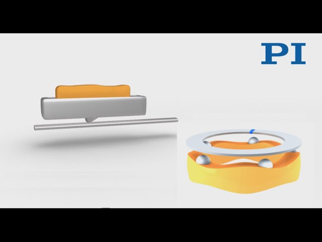
Other Basic Actuators
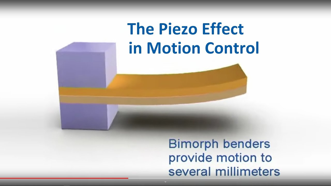
In addition to piezo stacks, a number of other basic Piezo actuators are available: bender actuators providing long travel (millimeter range), contraction actuators, tube actuators, shear actuators etc. (click here for more information)
Piezo Actuators with Motion Amplifiers & Trajectory Control
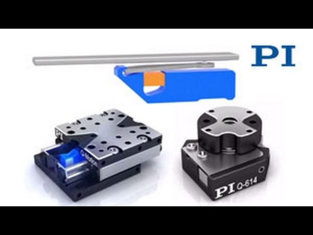
In some applications a stack actuator alone is not enough to perform complex tasks. For example, when straight motion is needed and only nanometer deviation from the ideal trajectory can be tolerated, a stack translator cannot be used because it may tilt as much as a few 10 arcseconds while expanding. If the stack and the part to be moved are decoupled and a precision guiding system is employed, exceptional trajectory control can be achieved. The best guiding precision can be achieved with flexures.

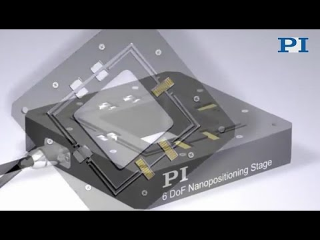
shows one example of a piezoelectrically driven miniature flexure stage with integrated flexure guiding system and motion amplifier. The stage is made of stainless steel and all flexures are wire EDM (Electrical Discharge Machining) cut. The flexures are computer designed by an FEA (Finite Element Analysis) program. The central part of the stage can move +/- 40 micrometers along one axis. The movement is accomplished by an integrated 3:1 lever driven by a Piezo stack pushing a spherical tip constructed integrally to the lever. The resonant frequency of the unloaded stage is 1 kHz (high when the lever amplification is considered).
The lever is connected to the platform by a flat spring which is very stiff in the push/pull direction but flexible in the lateral direction. This flexibility ensures straight stage motion with minimum tilt and lateral deviation. The system runout and flatness are less than 5 nanometers and even this low figure can be reduced with a larger flexure base (sub-nanometer, sub-microradian flatness can be achieved with actively error compensated multi-axis systems. The flexure design is not limited to single axis stages; systems with up to six degrees of freedom are available.
Single- and multi-axis flexure positioners are used in research, laboratory and industrial applications such as disk drive testing, mask aligners for X-Ray steppers, adaptive optics, precision machining, fiber aligners, scanning microscopy, autofocus systems for surface profilers and hydraulic servo valves.
Piezo Positioners combined with Motorized Long Range Positioning Systems
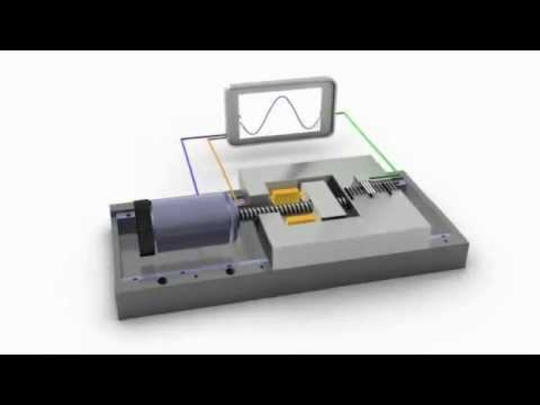
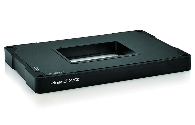
Piezo positioning systems can be combined with other positioning devices to form long range, high resolution systems. A good example is the F-130-series combination of a 3-axis piezo positioner (fine) and a motorized XYZ lead screw-driven stage (coarse). This combination provides up to 25 mm range (versions with 50 mm are available) but preserves the nanometer resolution characteristics intrinsic to piezo positioners PZTs. Sub-micrometer level coarse motion is provided by a motorized lead screw positioner driven by a DC motor/encoder/gearhead unit capable of 50 nanometer incremental motion. A 100 micron travel XYZ piezo positioner providing sub-nanometer capability is mounted on top. Both piezo positioner and DC motors are be computer controlled and can perform high speed precision motion and alignment tasks..
 and a piezo three-axis stage for long travel with nanometer precision")
Piezo actuators offer unique and compelling advantages in nanometer resolution and high speed applications. To obtain maximum performance while avoiding problems, however, piezoelectric characteristics need to be considered. Pulling, shear and torsional forces need to be controlled by the mechanical design. Standard Piezo ceramics run at operating temperatures to 150°C with high temperature options to 200°C. Modern PICMA piezo ceramics provide 100 billions of cycles of lifetime and extra protection from humidity.
Close contact between the Piezo user and the manufacturer assures the right actuator design is chosen for your application. PI has many decades of experience in designing piezoelectric positioners and systems and offers a wide variety of options which can adapt piezo motion devices to various environmental conditions.
If you have any questions, ask a PI engineer for help.