


Electrical Requirements for Piezo Operation
General
When operated far below the resonant frequency a Piezo behaves as a capacitor where displacement is proportional to charge (first order estimation).
Piezo stack actuators are assembled with thin wafers of electroactive ceramic material electrically connected in parallel.

The (small signal) capacitance of a stack actuator can be estimated by
C ≈ n*ε0*ε33*A/ds (4-14)
Where
n = number of layers
ε0 = dielectric constant in vacuum [As/Vm]
ε33 = relative dielectric constant [without Dimensions]
A = electrode surface area [m²]
ds = distance between the individual electrodes (layer-thickness) [m]
The above equation shows that for a given actuator length l0 and a given disk thickness d0 capacitance is a quadratic function of the ratio d0 / d1 where d1 < d0. Therefore, the capacitance of a piezo actuator constructed of 100 µm thick layers is 100 times the capacitance of an actuator with 1 mm thick layers if the two actuators are the same length.

Static Operation
When electrically charged, the energy E = 1/2 CU2 is stored in a piezo actuator. Every change in the charge (and therefore in the displacement) of the Piezo requires a current i:
i= dQ/dt = C * (dU/dt) (4-15)
Relationship of current and voltage for the piezo actuator
Where
i = current [A]
Q = charge [Coulomb; As]
C = capacitance [Farad; As/V]
U = voltage [V]
t = time [s]
For static operation only the leakage current has to be supplied. The high internal resistance reduces leakage currents to micro-amp or sub-micro-amp range. Even when disconnected from the electrical source, the charged actuator will not make a sudden move but return to its uncharged Dimensionss very slowly (> 1 hour).
For slow position changes, very low current is required. For example an amplifier with an output current of 20 µA fully expands a 20 nF actuator within one second.
Low Voltage PZTs (100 µm layers, 100 V operating voltage, high capacitance) require 10 times the driving current of High Voltage PZTs of similar size (1 mm layers, 1000 V operating voltage, low capacitance). Power requirements are similar. PI High/Low Voltage amplifiers are specially designed to meet the different requirements for driving High/Low Voltage actuators.
Dynamic Operation (Analog)
PZTs can provide accelerations of thousands of g's and are perfectly suited for dynamic applications.
Several parameters influence the dynamics of a Piezo positioning system:
Mechanical considerations:
- If the piezo element is installed in a positioning mechanism (and sufficient electrical power from the amplifier is available), the maximum drive frequency can be limited by dynamic forces.
- The maximum operating frequency is also limited by the phase and amplitude response of the system (especially in closed loop systems). Rule of thumb: the higher the system resonant frequency the better the phase and amplitude response and the higher the usable frequency.
Electrical considerations:
- The amplifier output current and rise time determine the maximum operating frequency of a piezoelectric system.
- In closed loop operation other parameters such as sensor bandwidth, phase margins and control algorithms determine the performance of a positioning system.
The following equations describe the relationship between amplifier output current, voltage and operating frequency. They help determine the minimum specifications of a Piezo amplifier for dynamic operation.
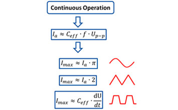
iA ≈ f * C * Up-p (4-16)
Average current required for sinusoidal operation
imax ≈ f * p * C * Up-p (4-17)
Peak current required for sinusoidal operation
fmax ≈ imax/(2 * C * Up-p) (4-18)
Maximum operating frequency with triangular ave form as a function of the amplifier output current limit
Where
iA = average amplifier source/sink current [A]
imax = peak amplifier source/sink current [A]
fmax = maximum operating frequency [Hz]
C = Piezo actuator capacitance [Farad (As/V)]
Up-p = peak-peak drive voltage [V]
f = operating frequency [Hz]
The average current and maximum current for each PI Piezo amplifier can be found in the technical data.
Example:
Q: What peak current is required to operate a HVPZT actuator with a nominal displacement of 40 µm @ 1000 V and capacitance of 40 nF with a sinusoidal wave form of 1000 Hz at 20 mm displacement?
A: With a nominal displacement of 40 mm @ 1000 volts, approximately 500 Vp-p are required to expand the actuator by 20 mm. With equation 4-17 the peak current is calculated to be » 63 mA. (Matching amplifiers can be found in the "Piezo Control Electronics" section of this catalog).
The following equations describe the relationship between (reactive) drive power, actuator capacitance, operating frequency and drive voltage.
The average power a piezo driver has to be able to provide for sinusoidal operation is
Pa ≈ C * Umax * Up-p * f (4-19)
Peak power for sinusoidal operation is:
Pmax ≈ p * C * Umax * Up-p * f (4-20)
Where
Pa = average power [W]
Pmax = peak power [W]
C = Piezo actuator capacitance [Farad (As/V)]
f = operating frequency [Hz]
Up-p = peak-peak drive voltage [V]
Umax = maximum output voltage swing of the amplifier [V]
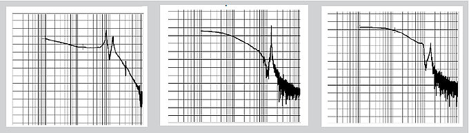
The Piezo capacitance values indicated in the technical data tables are small signal values (measured at 1 V, 1000 Hz, 20° C, no load). The capacitance of Piezo ceramics changes with amplitude, temperature, and load, up to 200% of the unloaded, small signal capacitance at room temperature. For detailed information on power requirements, refer to the amplifier frequency response graphs in the "Piezo Control Electronics" section of this catalog.
Instead of calculating the required drive power for a given application, it is easier to calculate the drive current because it grows linearly with both frequency and voltage (displacement). Output current capability for all PI High Voltage and Low Voltage amplifiers is given in the technical data tables (section "Piezo Control Electronics").
If you have any questions, ask a PI engineer for help.