Piezo Motion/ Piezo Drive Circuits: Electrical Requirements for Piezo Operation
Dynamic Operating Current Coefficient (DOCC) The Dynamic Operating Current Coefficient (DOCC) value is provided for each PI piezo translator to facilitate selection of the appropriate drive/control electronics. The DOCC is the electrical current (supplied by the amplifier) required to drive a Piezo per unit frequency (Hz) and unit displacement (sinewave operation). E.g. to find out if a selected amplifier can drive a given Piezo at 50 Hz with 30 µm amplitude, multiply DOCC by 50 and 30 and check if the result is less than or equal the average output current of the selected amplifier.
Dynamic Operation (Switched)
For applications such as shock wave generation or valve control, switched operation (on/off) may be sufficient. PZTs can provide motion with rapid rise and fall times with accelerations up to thousands of g's.
The simplest form of binary drive electronics for Piezo applications would consist of a large capacitor that is "slowly" charged and rapidly discharged across the Piezo.
Equation 4-21 relates applied voltage (which corresponds to displacement) to time.
U(t) = Uo + Up-p * (1-e-t/RC) (4-21)
Voltage on the piezo after switching event.
Where
U0 = start voltage [V]
Up-p = peak-peak drive voltage [V]
R = resistance in piezo drive circuit [W]
C = Piezo actuator capacitance [Farad (As/V)]
The voltage rises or falls exponentially with the RC time constant. Under static conditions the expansion of the Piezo is proportional to the voltage. In reality, dynamic Piezo processes cannot be described by a simple equation. Whenever the Piezo expands or contracts, dynamic forces act on the ceramic material. These forces generate a (positive or negative) voltage in the piezo element which adds to the drive voltage. A Piezo can reach its nominal displacement in approximately 1/3 of the period of the resonant frequency. For example, a piezo element with 10 kHz resonant frequency can reach its nominal displacement within 30 µs if amplifier current and rise time are sufficient.
If the voltage rises fast enough to excite a resonant oscillation in the Piezo, ringing and overshoot will occur.
For charging with constant current (e.g. provided by a linear amplifier), the following equation applies:
t » C * (Up-p/imax) (4-22)
Time to charge a Piezo with constant current. (Minimum amplifier rise time must also be considered).
Where
t = time to charge to Up-p [s]
C = Piezo actuator capacitance [Farad (As/V)]
Up-p = peak-peak drive voltage [V]
imax = peak amplifier source/sink current [A]
For fastest settling, switched operation is not the best solution. If the input signal rise time is limited to 1/f0 the overshoot can be reduced significantly. Pre-shaped input signals (optimized for minimum resonance excitation) reduce the time to reach a stable position.
Heat Generation in a Piezo at Dynamic Operation As mentioned before, PZTs are reactive loads and therefore require charge and discharge currents that increase with operating frequency. The thermal heat, P, generated in the actuator can be estimated with the following equation:
P » tan d * f * C * Up-p2 (4-23)
Heat generation in a Piezo.
Where
P = power converted to heat [W]
tan d = tangent of the loss angle (ratio of parallel resistance to parallel reactance)
f = operating frequency [Hz]
C = Piezo actuator capacitance [Farad (As/V)]
Up-p = peak-peak drive voltage [V]
For standard actuator Piezo ceramics the loss factor is on the order of 0.01 to 0.02 (large signal conditions, smaller for small signal conditions). This means that up to 2% of the electrical power pumped into the actuator is converted to heat. Therefore, the maximum operating temperature can limit the Piezo dynamics. For large amplitude and high frequency, operation cooling measures may be necessary. A temperature sensor mounted on the ceramics is suggested for monitoring purposes.
PI is currently investigating the design of new Piezo materials showing extremely low loss angles while still displaying a large d33 effect. These types of ceramics will allow high-frequency, long-term operation without cooling measures.
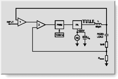
In addition, a new generation of amplifiers employing energy recovery technology has been developed for high power applications. shows the block diagram of such an amplifier. Instead of dissipating the reactive power at the heat sinks, only the active power used by the piezo actuator has to be delivered. The energy not used in the actuator is returned to the amplifier and reused as supply voltage by a step-up transforming process. The combination of low loss, high energy Piezo ceramics and amplifiers with energy recovery are the key to new high-dynamic piezo actuator applications in the near future.
If you have any questions, ask a PI engineer for help.
