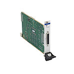
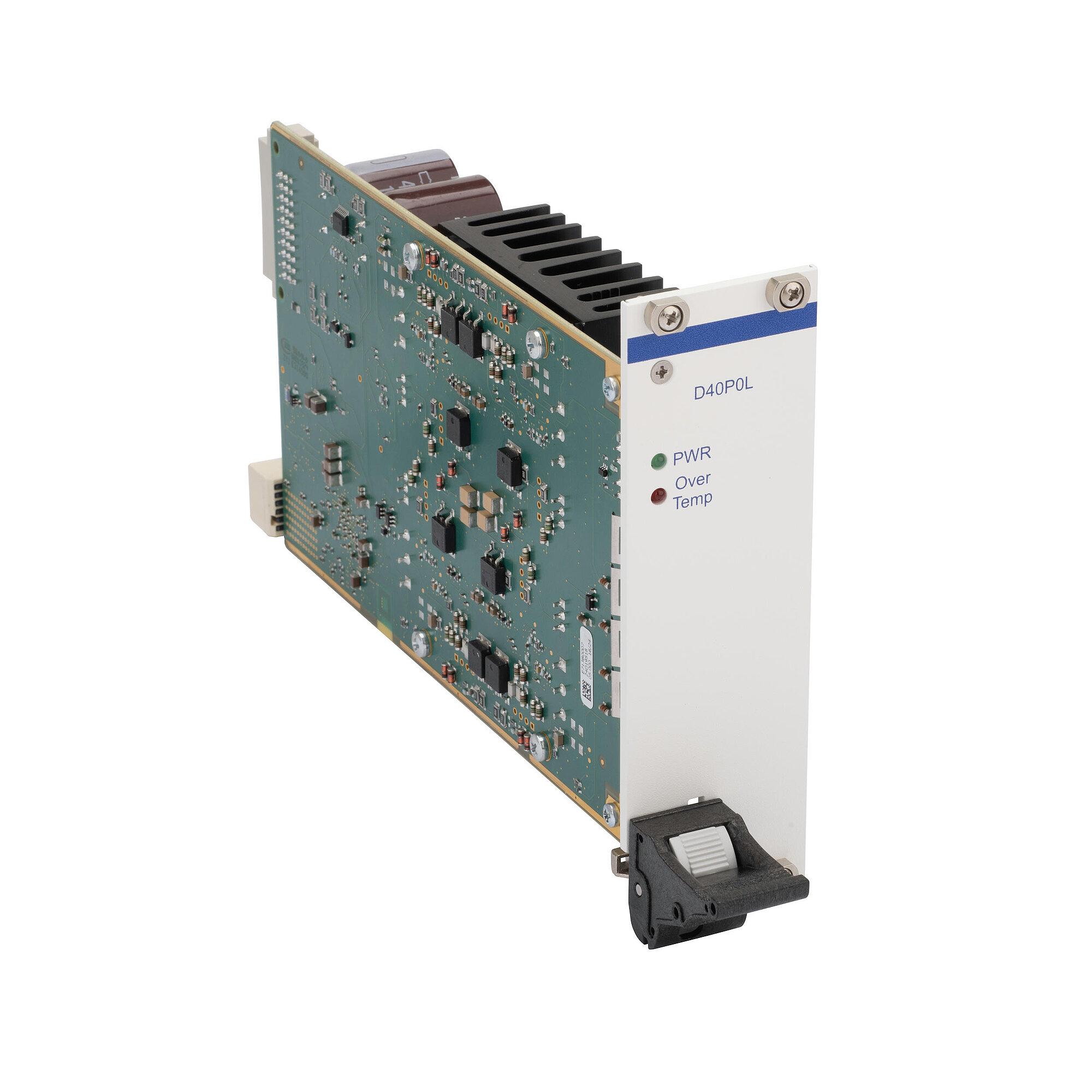
E-713.D40P0L NEW!
Amplifier module for piezo actuators, for modular E-713 Motion Controller, 4 channels, 8 W, -30 V to +135 V, no connector


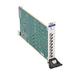
Amplifier for piezo-based drives
Motion control of PI positioning systems with piezo-based drive: depending on the model, up to 4 PICMA piezo actuators or 1 PICMAWalk or NEXLINE® type PiezoWalk® drive.
Sensor types
Depending on the model, 1 position sensor per PiezoWalk® drive. Sin/Cos sensor signal or sensor input via BiSS.
Connection variants
Reduced mechanical cabling effort through connector bundling, e.g., for amplifier outputs and sensor signals or for the outputs of multiple amplifier modules.
Modular design
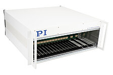
The amplifier modules are intended for use in the modular E-713 Motion Controller. The modular concept makes it possible to assemble E-713 Motion Controllers exactly according to customer requirements. An E-713 Motion Controller controls in a coordinated manner up to 16 axes with various drive types. This involves the use of state-of-the-art control and linearization algorithms. Optional digital and analog interfaces support motion automation.
| Basics | E-713.D40P0L | E-713.D40P0LO | E-713.D41PBL | E-713.D41PIL | E-713.D40P0MO | E-713.D40P0MI | E-713.D41PBM | E-713.D41PIM | |
|---|---|---|---|---|---|---|---|---|---|
| Housing type | Module without housing, 8 HP | Module without housing, 8 HP | Module without housing, 8 HP | Module without housing, 8 HP | Module without housing, 8 HP | Module without housing, 8 HP | Module without housing, 8 HP | Module without housing, 8 HP | |
| Drive type | PICMA® | PICMA® | PICMAWalk | PICMAWalk | NEXLINE® piezo walking drive | NEXLINE® piezo walking drive | NEXLINE® piezo walking drive | NEXLINE® piezo walking drive | |
| Output channels | 4 | 4 | 1 | 1 | 1 | 1 | 1 | 1 | |
| Input channels | — | — | 1 | 1 | — | — | 1 | 1 | |
| Protective functions | Deactivation of the voltage output in case of internal overheating | Deactivation of the voltage output in case of internal overheating | Deactivation of the voltage output in case of internal overheating | Deactivation of the voltage output in case of internal overheating | Deactivation of the voltage output in case of internal overheating | Deactivation of the voltage output in case of internal overheating | Deactivation of the voltage output in case of internal overheating | Deactivation of the voltage output in case of internal overheating | |
| Supported ID chip | ID chip 2.0 | ID chip 2.0 | ID chip 2.0 | ID chip 2.0 | ID chip 2.0 | ID chip 2.0 | ID chip 2.0 | ID chip 2.0 | |
| Motion and control | E-713.D40P0L | E-713.D40P0LO | E-713.D41PBL | E-713.D41PIL | E-713.D40P0MO | E-713.D40P0MI | E-713.D41PBM | E-713.D41PIM | |
| Supported sensor signal | — | — | BiSS-C | Sin/cos, 1 V peak-to-peak | — | — | BiSS-C | Sin/cos, 1 V peak-to-peak | |
| Reference switch input | — | — | TTL, Zero+ & Zero- | TTL, Zero+ & Zero- | — | — | TTL, Zero+ & Zero- | TTL, Zero+ & Zero- | |
| Limit switch input | — | — | TTL | TTL | — | — | TTL | TTL | |
| Interfaces and operation | E-713.D40P0L | E-713.D40P0LO | E-713.D41PBL | E-713.D41PIL | E-713.D40P0MO | E-713.D40P0MI | E-713.D41PBM | E-713.D41PIM | |
| Display and indicators | Power LED ǀ Overtemp LED | Power LED ǀ Overtemp LED | Power LED ǀ Overtemp LED | Power LED ǀ Overtemp LED | Power LED ǀ Overtemp LED | Power LED ǀ Overtemp LED | Power LED ǀ Overtemp LED | Power LED ǀ Overtemp LED | |
| Amplifier | E-713.D40P0L | E-713.D40P0LO | E-713.D41PBL | E-713.D41PIL | E-713.D40P0MO | E-713.D40P0MI | E-713.D41PBM | E-713.D41PIM | |
| Resolution DAC/voltage resolution | 20 bit | 20 bit | 20 bit | 20 bit | 20 bit | 20 bit | 20 bit | 20 bit | |
| Sensor | E-713.D40P0L | E-713.D40P0LO | E-713.D41PBL | E-713.D41PIL | E-713.D40P0MO | E-713.D40P0MI | E-713.D41PBM | E-713.D41PIM | |
| Maximum sensor interpolation factor | — | — | 65536 | 524288 | — | — | 65536 | 524288 | |
| Sensor bandwidth | — | — | — | 250 kHz | — | — | — | 250 kHz | |
| Electrical properties | E-713.D40P0L | E-713.D40P0LO | E-713.D41PBL | E-713.D41PIL | E-713.D40P0MO | E-713.D40P0MI | E-713.D41PBM | E-713.D41PIM | |
| Output voltage | -30 to +135 V | -30 to +135 V | -30 to +135 V | -30 to +135 V | -250 to +250 V | -250 to +250 V | -250 to +250 V | -250 to +250 V | |
| Short-circuit proof | Yes | Yes | Yes | Yes | Yes | Yes | Yes | Yes | |
| Average output power per channel | 8 W | 8 W | 8 W | 8 W | 15 W | 15 W | 15 W | 15 W | |
| Peak output power per channel | 25 W | 25 W | 25 W | 25 W | 45 W | 45 W | 45 W | 45 W | |
| Peak output power per channel, time limit | 5 ms | 5 ms | 5 ms | 5 ms | 5 ms | 5 ms | 5 ms | 5 ms | |
| Average output current per channel | 150 mA | 150 mA | 150 mA | 150 mA | 60 mA | 60 mA | 60 mA | 60 mA | |
| Peak output current per channel | 250 mA | 250 mA | 250 mA | 250 mA | 180 mA | 180 mA | 180 mA | 180 mA | |
| Peak output current per channel, time limit | 5 ms | 5 ms | 5 ms | 5 ms | 5 ms | 5 ms | 5 ms | 5 ms | |
| Miscellaneous | E-713.D40P0L | E-713.D40P0LO | E-713.D41PBL | E-713.D41PIL | E-713.D40P0MO | E-713.D40P0MI | E-713.D41PBM | E-713.D41PIM | |
| Motor/actuator connector | — | D-sub 25W3 | D-sub 37 (f) | D-sub 37 (f) | D-sub 25 (f) | — | D-sub 25 (f) | D-sub 25 (f) | |
| Sensor connector | — | — | D-sub 37 (f) | D-sub 37 (f) | — | — | D-sub 25 (f) | D-sub 25 (f) | |
| Operating temperature range | 5 to 40 °C | 5 to 40 °C | 5 to 40 °C | 5 to 40 °C | 5 to 40 °C | 5 to 40 °C | 5 to 40 °C | 5 to 40 °C | |
| Overall mass | 515 g | 515 g | 515 g | 515 g | 515 g | 515 g | 515 g | 515 g |
With the amplifier modules for PICMAWalk drives and NEXLINE® drives, the output channel corresponds to what is known as a PiezoWalk channel. Internally, up to 4 amplifier channels of the module may be involved in controlling the drive through the PiezoWalk channel.
The E-713.D40P0L amplifier module does not have a connector for positioning systems, but rather the voltage output for the piezo actuators is effected via the connector of a module for capacitive sensors or strain gauge sensors. For this reason, the E-713 Motion Controller must contain a corresponding sensor processing module for each E-713.D40P0L amplifier module.
The E-713.D40P0MI amplifier module has an internal connector. The voltage output for up to 6 E-713.D40P0MI amplifier modules is available via an HD D-sub-50 (f) connector on the E-713.R3 housing.
GCS commands for E-713 modular Motion Controller system
E-713 modular Motion Controller system
Ask for a free quote on quantities required, prices, and lead times or describe your desired modification.
Amplifier module for piezo actuators, for modular E-713 Motion Controller, 4 channels, 8 W, -30 V to +135 V, no connector
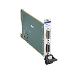
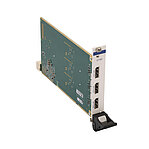
Amplifier module for piezo actuators, for modular E-713 Motion Controller, 4 channels, 8 W, -30 V to +135 V, D-sub 25W3
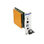
Amplifier module for PICMAWalk, for modular E-713 Motion Controller, -30 V to +135 V, sensor input via BiSS, D-sub 37 (f)
Amplifier module for PICMAWalk drive with incremental encoder, for modular E-713 Motion Controller, -30 V to +135 V, D-sub 37 (f)
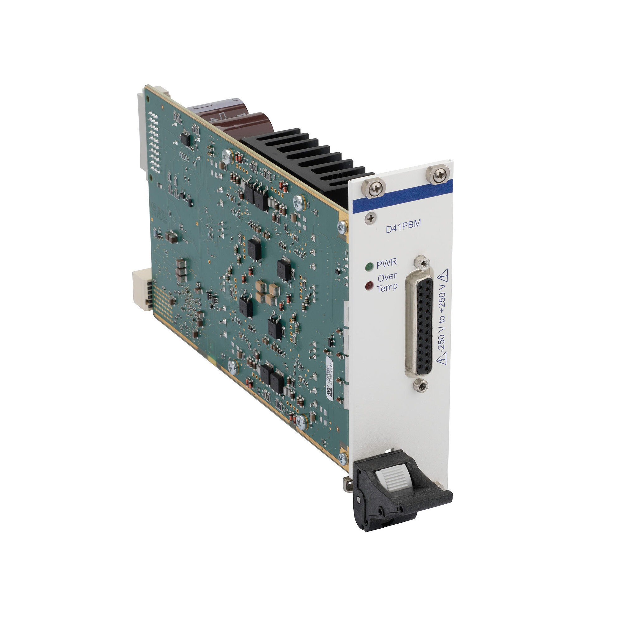
Amplifier module for NEXLINE®, for modular E-713 Motion Controller, -250 V to +250 V, D-sub 25 (f)
Amplifier module for NEXLINE®, for modular E-713 Motion Controller, -250 V to +250 V, internal connector
Amplifier module for NEXLINE®, for modular E-713 Motion Controller, -250 V to +250 V, sensor input via BiSS, D-sub 25 (f)
Amplifier module for NEXLINE® drive with incremental encoder, for modular E-713 Motion Controller, -250 V to +250 V, D-sub 25 (f)