Mechanical Considerations for Dynamic Operation of PZTs
Dynamic Forces
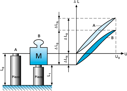
Every time the Piezo drive voltage changes, the piezo element changes its Dimensionss (if not blocked). Due to the inertia of the Piezo mass (plus any additional mass), a rapid change will generate a force (pushing or pulling) acting on the piezo. The maximum force is equal to the blocked force described by:
Fmax ≈ ± kT*ΔL0 (4-8)
Maximum force available to accelerate the piezo mass plus any additional mass.
where
ΔL0 = max. nominal displacement without external force or restraint [m]
kT = Piezo actuator stiffness [N/m]
Tensile forces must be compensated for by a mechanical preload (inside the actuator or external) in order to prevent damage to the ceramics. Preload should be around 20 % of the compressive load limit, with soft preload springs soft compared to the Piezo stiffness (1/10 or less).
In sinusoidal operation with frequency f and the amplitude DL/2, peak forces can be expressed as
Fdyn = ±4π2*meff*(ΔL/2)*f2 (4-9)
Dynamic forces on a Piezo in sinusoidal operation with frequency f.
where
Fdyn = dynamic force [N]
meff .= effective mass [kg]
ΔL = peak to peak displacement [m]
f = frequency [Hz]
The maximum permissible forces must be considered when choosing an operating frequency.
Example:
Dynamic forces at 1000 Hz, 2 µm peak-peak, 1 kg load are approximately ± 40 N.
Note:
A guiding system (e.g. diaphragm type) is recommended when heavy loads or large mechanical parts (compared to the piezo actuator diameter) are moved dynamically. Without a guiding system there is a potential for tilt oscillations and other non-axial forces that may damage the Piezo ceramics.
Resonant Frequency
In general, the resonant frequency of any spring/mass system is a function of its stiffness and effective mass. The resonant frequency given in the technical data tables always refers to the unloaded actuators, rigidly mounted on one end.
f0 = (1/2π)*√(kT/meff) (4-10)
Resonant frequency of an ideal spring/mass system.
where
f0 = resonant frequency [Hz]
kT = actuator stiffness [N/m]
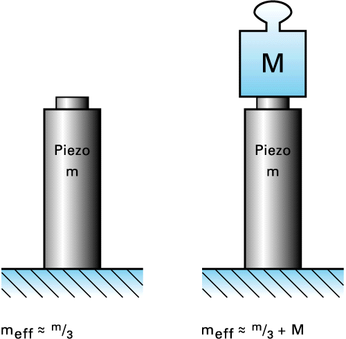
meff = effective mass (about 1/3 of the mass of the ceramic stack plus any installed end pieces) [kg]
Note:
Due to the non-ideal spring behavior of Piezo ceramics, the theoretical result of the above equation does not necessarily match the real-world behavior of a Piezo system.
When adding a mass to the actuator the resonant frequency drops according to the following equation:
f0'=f0 √(meff/(meff+M)) (4-11)
Resonant frequency with additional mass M.
The above equations show that increasing the mass on the actuator by a factor of 4 will reduce the response (resonant frequency) by a factor of 2. Increasing the spring preload on the actuator does not significantly affect its resonant frequency.
The phase response of a Piezo system can be approximated by a second order system and is described by
φ ≈ 2 * arc tan (f/f0) (4-12)
φ = phase angle [deg]
f0 = resonant frequency [Hz]
f = operating frequency [Hz]
How Fast Can a Piezo Actuator Expand? Fast response is one of the desirable features of piezo actuators. A rapid drive voltage change results in a rapid position change. This property is necessary in applications such as switching of valves/shutters, generation of shock-waves, vibration cancellation systems, etc.
A Piezo can reach its nominal displacement in approximately 1/3 of the period of the resonant frequency with significant overshoot.

Tmin ≈ fo/3 (4-13)
Shortest rise time of a piezo actuator (requires an amplifier with sufficient output current and rise time).
For example, a piezo translator with a 10 kHz resonant frequency can reach its nominal displacement within 30 µs.
If you have any questions, ask a PI engineer for help.
