


Basic Designs of Piezoelectric Positioning Elements: Piezo Flexure Guided Stages and Actuators
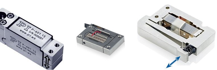
Piezo Actuators and Stages with Integrated Lever Motion Amplifier
Piezo actuators or positioning stages can be designed in a way that a lever motion amplifier is integrated into the system, increasing the Piezo displacement by a factor of typically 2 to 20. To maintain high resolution and fast response with the increased travel range, the leverage system must be stiff, backlash- and friction-free which is why ball or roller bearings cannot be used. PI employs a proprietary Finite Element Analysis (FEA) computer program to design Piezo Flexure NanoPositioners with or without inte-grated lever motion amplifiers . Piezo positioners with integrated motion amplifier have several advantages over standard piezo actuators:
- guided motion, decoupling of forces from the ceramics
- compact size compared to stack actuators with equal displacement
- reduced capacitance (= reduced drive current)
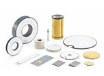
 is given by (a+b)/a. Bimorph design (strip and disk translator).")

Flexure positioners are far superior to traditional positioners (ball bearings, crossed roller bearings, dovetails etc.) in terms of resolution, straightness and flatness. Inherent friction and stiction in these traditional designs limit applications to those requiring repeatability on the order of 0.5 to 0.1 µm.
For applications where extremely straight motion in one or more axes is needed and only nanometer deviation from the ideal trajectory can be tolerated, stacks, tubes and other basic actuators are not ideal because they may exhibit too much off-axis error. At the same time they may not yield sufficient motion in a small enough package. PI Piezo Flexure NanoPositioners with passive or active trajectory control provide an excellent solution to the above problems.
A flexure is a frictionless, stictionless device based on the elastic deformation (flexing) of a solid material. Sliding and rolling are entirely eliminated. In addition to absence of internal friction, flexure devices exhibit high stiffness and load capacity. Flexures are also less sensitive to shock and vibration than other guiding systems.
Basic parallelogram flexure actuators show a second-order cross coupling (parasitic motion) between axes. This movement is called arcuate motion (travel is in an arc motion). It can lead to small out-of-plane errors on the order of 0.1% of the distance traveled ( The error can be estimated by the following equation:
ΔH ≈ (±ΔL/2)² /2H (4-28)
where
ΔH = Lateral runout (out-of-plane error) [m]
ΔL = Distance trav-eled [m]
H = Length of the flexures [m]
For applications where this error is undesirable, PI has designed a zero-runout multi-flexure guiding system. This special design, employed in most PI flexure stages eliminates the cross coupling inherent in common parallelo-gram guiding systems and provides flatness and straightness in the nanometer and micro-radian range, respectively. The excellent bidirectional trajectory repeatability of PI's design allows for higher throughput in demanding applications.
For applications requiring sub-nanometer and sub-µrad flatness and straightness, PI offers a system with integrated multi-axis error compensation (active trajectory control). It measures and actively controls motion in all six degrees-of-freedom to sub-nanometer and sub-microradian tolerances. The exceptional flatness provided by this system is shown in.
 of an actively error compensated flexure stage over a 100 x 100 µm scanning range.")
If you have any questions, ask a PI engineer for help.