Precision Motion and Positioning: Difference between Micropositioning and Nanopositioning
Micropositioning refers to mechanical movements with positioning accuracy and resolution in the micron or sub-micron range. Nanopositioning refers to positioning with nanometer or sub-nanometer resolution.
Design rules for motion systems with millimeter or sub-millimeter resolution do not always apply for the micron and sub-micron range. Resolution in the sub-micron realm cannot always be increased by simple means such as reducing the pitch of a leadscrew or increasing the gear ratio of motor/ gearhead unit. Stiction/friction, play, backlash, wind up effects, tilt, temperature effects, etc. will also limit accuracy and resolution. Sub-micron positioning systems require a great deal of attention in the design, manufacturing and selection of materials.
PI has several decades of experience in designing motorized micropositioning stages and nanopositioning stages for a wide range of applications, including piezo flexure guided nanopositioning systems, air bearing stages, linear, rotation and tilting stages, driven by piezo motors, servo motors, linear motors, rotary motors and stepper motors.
Quality Management at PI
PI has been ISO9001 certified since 1994. PI’s capabilities include a state-of-the-art vibration isolated and 0.1 degree temperature controlled sub-nanometer metrology lab to certify the performance of our products. Interferometers, auto collimators and several other ultra-high resolution metrology systems are employed to measure the Guiding and Position Accuracy of our micropositioning and nanopositioning products.

Micropositioning Terms
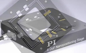
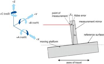
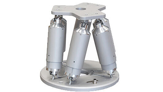
Definition of Axes and Angles
X: Linear motion in positioning direction
Y: Linear motion perpendicular to positioning direction
Z: Vertical linear motion
θX: Angular motion around X (roll)
θY: Angular motion around Y (pitch)
θZ: Angular motion around Z (yaw)

Glossary
A more detailed Glossary on Micropositioning and Nanopositioning terms is here.
Absolute Accuracy
For any given input this is the maximum difference between the commanded (ideal) position and the actual position. Absolute accuracy is often confused with resolution. For real systems, resolution is usually a great deal higher than absolute accuracy which is affected by backlash, hysteresis, drift, linearity, and repeatability. Absolute accuracy in the range of 1 µm or better over more than a few mm of travel, can usually only be achieved with external measuring systems such as laser interferometers or linear glass scales. Leadscrew mounted encoders or stepper motors cannot achieve this kind of accuracy.
Backlash
Lost motion after reversing direction. This can be due to play in screw/nut fittings, gearheads, bearings, etc. Some manufacturers promote controllers with automatic backlash compensation adding the estimated amount of lost motion upon each reversal. A good solution in theory which is limited in practice because backlash varies with load, leadscrew position, temperature, deceleration, direction, wear etc. Backlash can lead to oscillation in closed loop set ups where the position sensor is directly attached to the part to be controlled. Backlash is not to be confused with hysteresis.
Bi-directional repeatability
The accuracy of returning to a position A from any position, regardless of direction. Effects such as hysteresis and backlash affect bi-directional repeatability. See Unidirectional Repeatability.
Cosine Error
A cumulative error that occurs when a drive system is misaligned in regard to the driven part. The error equals 1 – the cosine of the angle between the ideal drive axis and the actual drive axis times the moved distance.
DC Servo Motor
A direct current motor that is operated in a closed loop system (servo circuit). Vibrationless, smooth running, broad speed range and very good low speed torque are characteristics of DC servo motors. For optimum performance a good motor controller with PID (Proportional, Integral, Derivative) filter settings is mandatory.
Guiding Accuracy
See runout
Hysteresis
Hysteresis occurs when reversing direction. Unlike backlash which is lost motion at the beginning of a reversed motion, hysteresis contributes to position error by the relaxation of elastic forces in the drivetrain components. Hysteresis is highly variable based on different load and acceleration values.
Design Resolution
The theoretical minimum movement that can be made based on the selection of the mechanical drive components (drive screw pitch, gear ratio, angular motor resolution etc.). Design resolution is usually higher than the practical position resolution (minimum incremental motion). Examples where design resolution is higher than position resolution are motor/gear box driven systems with very high gear reduction ratio, or microstepped motors. A linear stage driven by such a motor can require an input of 1,000,000 steps (encoder counts) to move a distance of one mm. In this case one step performed and displayed by the motor controller is equal to 1 nanometer. In reality the stage may not be able to respond to motion input less than 50 steps due to play, windup, friction, backlash etc.
Minimum Incremental Motion
The minimum motion that can be repeatedly executed for a given input, which is sometimes referred to as practical or operational resolution. For systems with microstepped motors or motor / gearbox combinations design resolution and practical resolution have to be distinguished. Design resolutions of 1 nm or better can be achieved with many motor, gearbox and leadscrew combinations. In practical applications, however, stiction/ friction, windup, and elastic deformation limit resolution to fractions of a micron.
Repeatable nanometer or sub-nanometer resolution can only be provided by solid state actuators (PZTs) and PZT flexure stages (see "PZT Flexure NanoPositioners" and "PZT Actuators" sections for details). See also Design Resolution.
Orthogonality
The deviation from the ideal 90° angle between the X and Y axis.
Precision
An undefined term used differently by different manufacturers. Precision sometimes refers to absolute accuracy, repeatability, even to resolution.
Resolution
See Design Resolution and Minimum Incremental Motion. Resolution is often confused with accuracy.
Runout (Tracking Accuracy, Guiding Accuracy)
Deviation from a straight line. For linear stages, the runout describes unwanted motion in all 5 degrees of freedom (off-axes) other than the intended linear motion in the commanded direction. For a translation in X, linear runout occurs in Y and Z, tilt occurs in theta X (roll), theta Y (pitch) and theta Z (yaw). Runout is caused by the guiding system itself, by the way the stage is mounted (tension!) and the load conditions.
Stepper motor
An electric motor designed for open loop operation providing motion in discrete steps. Stepper motors provide limited dynamic properties compared to DC servo motors of equal size. They also dissipate more heat at steady state operation and produce noise and vibration during motion. Modern, 5 phase designs have mostly overcome these problems. Stepper controller design (open loop) is simple compared to DC servo controller design (closed loop). Stepper motors yield good results in predictable applications.
Stick/Slip Effect
Limits resolution. Caused by the fact that the coefficient of static friction is greater than the coefficient of dynamic friction. When a drive force is applied to a positioner the start of motion is out of phase with the build up of force. In the beginning no motion occurs and when a threshold is reached a sudden jump occurs. Only frictionless devices such as solid state actuators (piezo actuators) do not exhibit stiction and therefore provide superior resolution to "classical mechanical positioners" in the sub-micron to sub-nanometer realm.
Tracking Accuracy
See runout
Unidirectional Repeatability
The accuracy of returning to a given position from any other position, but always from one direction. Unidirectional repeatability is not affected by backlash. See Bi-directional Repeatability.
For more information, read our blog "Defining Micropositioning and Nanopositioning Terminology"

Straightness of travel, symmetrical movement and absence of backlash are especially important for precision mechanical positioning.
Magnetically coupled stages use the force of integrated magnets to preload the stage. Although not as good as
Air Bearings and flexure guides, they provide better straightness than is achieved with cross roller bearings.
This magnetic preload results in extremely uniform and smooth motion with minimum friction. To guarantee optimum straightness of travel only one of the two linear bearings guide the stage (V-grooves) while the second bearing only supports (U-grooves) the top platform. Straightness and flatness is better than 0.2 µm over 25 mm. Resolution with the optional PZT drive is better than 10 nm.
Due to the limited magnetic force only small loads can be handled in vertical applications. The same applies to lateral forces.
Linear Guiding Rods with Ball Bearings

Precision ground rods of hardened steel and linear ball bearings are used for the M-311 translation stages. A brass tube serves as ball cage. To reduce backlash and guarantee low friction the rods and ball bearings have to be matched with very tight tolerances.
Linear Rails with Double Row Recirculating Ball Bearings

Several types of motorized translation stages are equipped with precision double linear rails. The moving carriage is supported by a total of four preloaded linear bearings with two rows of recirculating balls each. The rails are bolted to the precision machined stage base by several screws. Precision assembly allows these bearings to yield excellent results in terms of straightness, smoothness and load capacity.
Leadscrews
A drive system consisting of a screw and a nut coupled to the carrier. Leadscrews are self-locking but exhibit higher friction (motor output power, max. velocity) than recirculating ballscrews. M-125, and M-400 stages are equipped with leadscrews. Standard PI leadscrews have a pitch of 0.5 mm/revolution.
Recirculating Ballscrews

Recirculating ballscrews reduce the sliding friction of leadscrews to rolling friction. They consist of a screw, a nut (ball housing) and a number of balls riding between the screw and the nut. When the screw rotates, the revolving balls transmit an axial movement to the housing attached to the carriage. Before the balls reach the end of the thread they recirculate to their original position through a channel in the housing. By selecting a certain ratio of ball diameter and thread diameter a backlash eliminating preload is generated.
Ballscrews show significantly reduced friction, wear and longer lifetime than leadscrews. They reach higher velocities than leadscrews with efficiencies up to 90 %. Ballscrews are not self-locking. M-500 stages are equipped with recirculating ball-screws. Standard PI ball-screws have pitches of 1 and 2 mm/revolution.
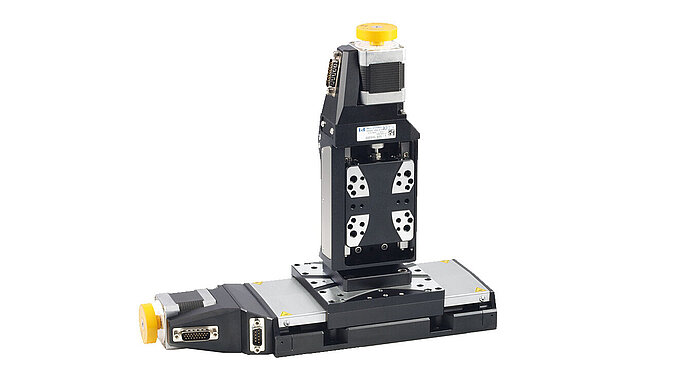
Almost any PI translation or rotation stage is available with a motor drive. Three different drives are available:
DC Motor Direct Drives
Advantages of DC motor direct drives are high speed, acceleration and absence of vibration. Low heat dissipation at rest and fast response (ideal for tracking and contouring applications) are further advantages.
Standard shaft mounted optical encoders provide resolution down to then anometer range. Highest positioning accuracy is achieved with integrated linear encoders.
DC Motor/Gearhead Drive
Advantages of DC motor/gearhead drives are very high angular resolution and low power consumption (can be operated by PC controller boards without external amplifier). 3 Watt DC motors with gearheads and motor shaft mounted encoders are used. Encoders provide 2000 and 60 counts/revolution, respectively. Zero backlash motor/gearhead combinations are available for improved repeatability.
5 Phase Stepper Motor Drives
High resolution 5-phase stepper motors with 2000 steps/rev. are used. Low vibration, high angular stiffness and exceptional angular accuracy are the benefits of 5-phase stepper motors. These factors provide considerable advantages over conventional 2/4-phase stepper motors, which must use electronic micro stepping techniques (with several disadvantages) to achieve comparable resolution. Compared to DC servo motors stepper motors are especially suited in applications where predictable point to point positioning is required rather than fast response and extreme acceleration.
DC-Mike Motorized Micrometer Drive Options
These micrometer replacement actuators have non rotating tip constructions driven by a 2 Watt DC servo motor/ gearhead with motor shaft mounted encoder. The units are used on some of our translation and rotation stages and feature sub-micron resolution.
PZT Piezoelectric Drive Options
Resolution on the order of 1 nm and better can be achieved with piezo actuators. Drive options are available for several of our translation and rotation stages. Piezo translators can move very fast and do not exhibit stiction/friction or backlash. See "PZT Actuators" for further information.

This is a legacy product that may have limited availability or may have been replaced. Ask a PI engineer for an equivalent new model.