

36 W Peak Power
Position Servo Control
For Strain Gages & LVDT Sensors
RS-232 Computer Interface with 12-bit D/A Converter

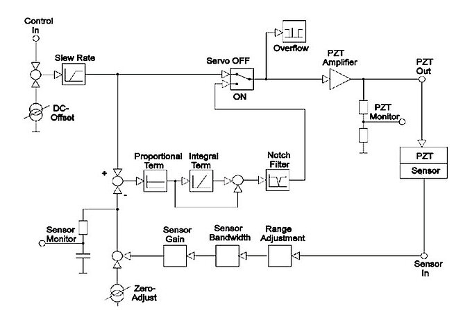
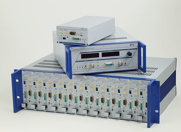
E-662 is a bench-top, closed-loop feedback servo controller with integrated high voltage piezo driver / amplifier. It also has a digital RS-232 computer interface and 12 bit D/A converter and can operate piezo nanopositioning stages and actuators. The piezo voltage amplifier can output and sink a peak current of 360 mA and an average current of 120 mA. The closed-loop piezo servo controller works with either strain gage sensors (E-662.SR) or LVDT sensors (E-662.LR). E-662 can be operated in 6 ways.

I. Open loop (amplifier / driver mode)
Manual operation
Piezo driver output voltage can be set by a 10-turn, DC offset potentiometer in the range of 0 to 100 V.
External operation
Piezo driver output voltage is controlled by an analog signal applied to the BNC input ranging from -2 to +12 V. Multiplying by the gain factor of 10, an output voltage range of -20 to +120 V results. The DC offset potentiometer allows for a continuous variation of the input voltage range between -2 V to +12 V and -12 V to +2 V.
Computer Control (toggle switch selected)
Piezo driver voltage is controlled via the RS-232 computer interface in the range of 0 to 100 V with a resolution of 12 bits. The DC offset potentiometer and BNC analog input are inactive when in computer control mode.

II. Closed loop position feedback servo control mode
Manual operation
Displacement of the piezo nanopositioning stage or piezo mechanism can be set by a 10-turn, DC offset potentiometer in the range of zero to nominal displacement.
External control operation
Displacement of the Piezo stage or mechanism is controlled by an analog signal in the range of 0 to +10 V, applied to the BNC input. The controller is calibrated in such a way that 10 V corresponds with maximum nominal displacement and 0 V corresponds with 0 displacement. The DC offset potentiometer can be used to add an offset voltage of 0 to 10 V to the input signal.
Computer Control (toggle switch selected)
Displacement of the Piezo nanopositioning stage / piezo mechanism is controlled via the RS-232 computer interface in the range of 0 to maximum nominal displacement, with a resolution of 12 bits. The DC offset potentiometer and BNC analog input are inactive when in computer control mode.
More than 40 SCPI (Standard Commands for Programmable Instruments) ASCII commands are available to program the E-662. An internal function generator provides sine, square, ramp and triangular functions up to 150 Hz. User defined functions can be stored in a table with up to 200 entries. Minimum time between two samples is 1 msec.
ORDERING INFORMATION:
E-662.LR Piezo Amplifier/ Closed-Loop Piezo Servo Controller, LVDT, RS-232 Interface
E-662.SR Piezo Amplifier/ Closed-Loop Piezo Servo Controller, SGS, RS-232 Interface
| TECHNICAL DATA: E-662 | |
Function | Power amplifier & |
Channels | 1 |
Amplifier | |
Maximum output | 36 W |
Average output power | 12 W |
Peak output current | 360 mA |
Average output current | 120 mA |
Current limitation | short-circuit proof |
Voltage gain | 10 ±0.1 |
Polarity | Positive |
Control input voltage | -2 to +12 V |
Output voltage | -20 to 120 V |
DC offset setting | 0 to 100 V |
Input impedance | 100 kW |
Display | 2 x 3 1/2 digit, LED |
Control input socket: | BNC |
PZT voltage output | LEMO ERA.00.250.CTL |
Dimensions | 288x235x103 mm |
Weight | 2.5 kg |
Operating voltage | 90-120 / 220-240 VAC, |
Position Servo Control | |
Sensor Types | strain gages |
Servo Characteristics | P-I (analog) |
Sensor socket | LEMO ERA.0S.304.CLL |
Sensor monitor | BNC |
D/A Converter & Computer Interface | |
Resolution | 12 bit (=^ 2.5 mV input) |
Computer interface | RS-232 |


This is a legacy product that may have limited availability or may have been replaced. Ask a PI engineer for an equivalent new model.