PI Piezo High Voltage Drivers, Amplifiers and Controllers - Power Requirements / Open Loop Frequency Response

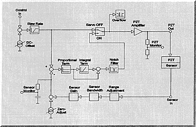
Analog, open loop piezo drivers / high voltage amplifiers without position servo control work according to the top branch of the diagram.
Also, the slew rate adjustment, servo ON/OFF switch and overflow indicator are only found on position servo controllers. Note that the DC-Offset is added to the input voltage before it is amplified.
The diagram shows that input voltage range of PI piezo drivers / amplifiers can be varied with the DC-Offset potentiometer. This principle is also valid for high voltage piezo amplifiers, where the typical input range is 0 to +10 V and the output range is 0 to -1000 V. The DC-Offset potentiometer allows for a continuously variable input range between 0V to +10V and -10V to 0V.
Digital closed loop controllers provide higher performance. Learn more on the comparison of analog controllers and digital piezo controllers.


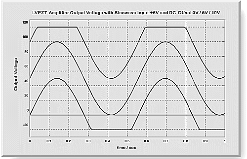
In order to achieve minimum distortion and clipping of the output waveform, it is important to reduce the control input amplitude into the high voltage piezo driver, when operating at higher frequencies with the same ratio the output voltage drops. Example: The E-503 (E-663) high voltage linear piezo amplifier can drive a 23 µF load at 100 V peak-peak (sine-wave) up to approximately 15 Hz. At higher frequencies, the output voltage drops off, e.g. to 80 V at 20 Hz. Therefore, it is important to reduce the input voltage amplitude to 8 V (gain = 10) at this frequency. Otherwise the amplifier will output a clipped sinewave.
The frequency response of a given amplifier depends on the amplifier power, the amplifier design, and, of course, the Piezo capacitance. For dynamic applications, PZTs require high charge and discharge currents. Those requirements are best met by power amplifiers that can source and sink high peak currents. The average current is of secondary importance. For exact information on maximum operating frequency with a given Piezo load, refer to the individual frequency response graphs.
For the highest output power up to 6000W, PI has developed a high voltage piezo amplifier with energy recovery.
Open loop frequency response data for all PI Piezo High Voltage Power Amplifiers in this catalog were taken after 15 minutes of continuous operation (Piezo and amplifier) at room temperature. After power up (cold conditions) maximum operating frequency is higher. The indicated capacitance values are small signal values for real PZTs (measured at 1 V, 1000 Hz, 20° C, no load). The capacitance of Piezo ceramics significantly changes with amplitude, temperature, and load, up to approximately 200% of the unloaded, small signal capacitance at room temperature. Therefore, the frequency response graphs actually reflect a higher load to the power amplifier than the capacitance values indicate.
For more information on Position Servo Control, please refer to "Tutorial: Piezoelectrics in Positioning" section.
When PI servo controllers are ordered together with external sensors (E-115 LVDT Sensors or D-015, D-050 or D-100 Capacitive Sensors), PI offers a special pre-calibration service free of charge. The controller will be prepared for the required travel range and the dynamic control circuit will be pre-adjusted for the expected resonance frequency of the system. When ordering external sensors, please provide the following information:
- Travel range of the Piezo positioning system to be controlled by the sensor
- Expected first resonance frequency of the system
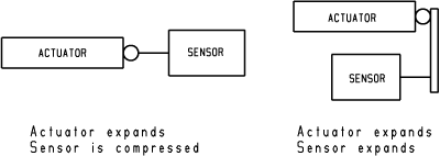
- Sensor direction: Will the sensor be compressed or will it expand when the Piezo Actuator expands (see sketch)
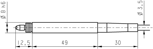
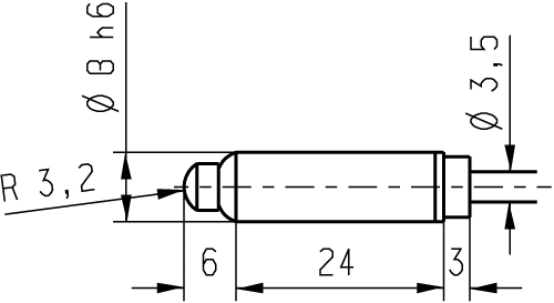
E-115 LVDT Position Sensors
E-115.11 and E-115.21 LVDT (Linear Variable Differential Transformer) Position Sensors can be used with E-509.L1, E-509.L3, E-610.L0 and E-662.LR Piezo Position Servo Controllers for quasi-static, closed loop operation of Piezo Actuators and Piezo NanoPositioning systems. When ordering, please specify the required positioning range and operating direction (increasing displacement = tip moving inwards or outwards, see drawing above), since the sensor circuit on the servo controller has to be adjusted accordingly. Resolution is on the order of 10-4 of the selected measuring range. For operating princple, see "Tutorial: Piezoelectrics in Positioning" section.
| TECHNICAL DATA: E-115.11, E-115.21 | ||
Models | E-115.11 | E-115.21 |
Function | LVDT Position Sensor | LVDT Position Sensor |
Measuring range | Max. ą 1 mm | Max. ą 0.5 mm |
Bandwidth | 5 Hz | 5 Hz |
Measurement force | 0.63 N | 0.63 N |
P-895.00, P-896.00 Extension Boards
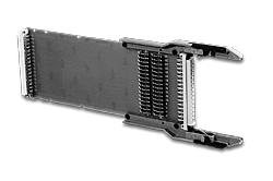
P-895.00 is used for the extension of the 32 pin connectors of plug in modules (e.g. E-503, E-507, etc.) for the E-500 and E-501 chassis. It is required for calibration and maintenance work. To allow the measurements of electrical current, all traces on the board are jumpered.
Note: E-515.i1, E-515.i3 and E-612.C0 are 64 pin modules requiring the P-896.00 extender board.
This is a legacy product that may have limited availability or may have been replaced. Ask a PI engineer for an equivalent new model.