Study – Interaction and Function of Nonmagnetic Ceramic Motors and Rotation Stages in Strong Magnetic Fields
Materials, Design, Test Data of PILine® Piezo Motor-Driven Positioning Stages in Magnetic Fields
1 Overview
There are several types of piezoelectric ceramic motors, such as resonant motors and inertia motors, that are employed as the driving force in precision motion systems, for example linear motion stages and rotary positioning stages. In this study, we are looking at direct-drive ultrasonic resonant motors known as PILine® motors. The direct-drive design enables very low response times and highly precise positioning performance without backlash. The preloaded operating principle of PILine® motors makes them hold a position even when powered-off. In addition, the piezoceramic drives are not influenced by magnetic fields and do not exhibit magnetic fields.
This blog aims to give a better understanding of the use of PILine® precision motion stages in strong magnetic fields, or in environments where the drive needs to behave neutrally in a magnetic sense.
2 Operating Principle of PILine® Ceramic Motor Positioning Systems
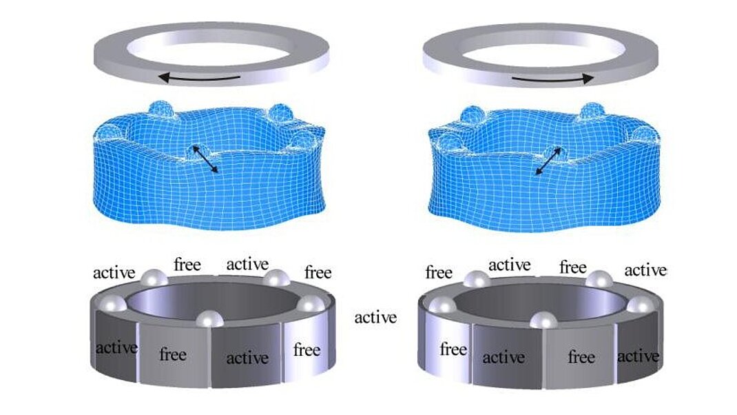
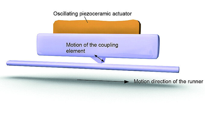
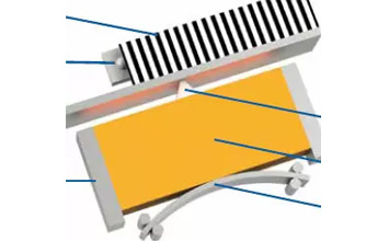
At the core of every PILine® motor driven linear or rotary stage is a piezoelectric actuator that is preloaded against a runner using a coupling element (see Fig. 1).
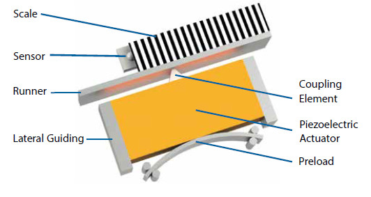
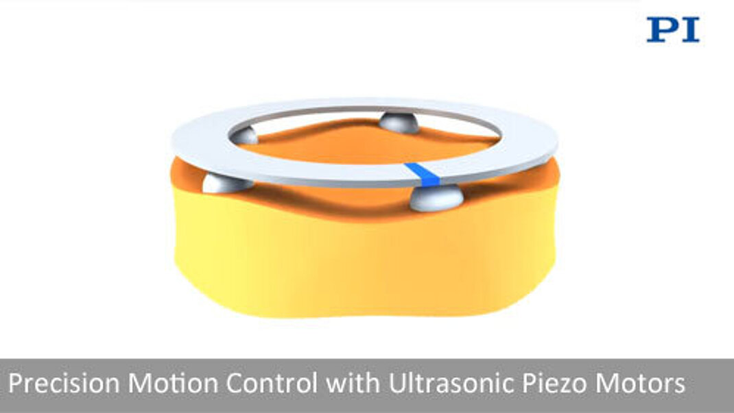
When an electric field is applied, the inverse piezoelectric effect causes the piezoceramic transducer to deform. The deformation takes place at crystalline level within the material and is hence, not affected by magnetism. That is why PILine® ultrasonic motors do not interact with magnetic fields.
These properties allow for two application fields for piezo motors:
- Operation in strong magnetic fields
- Use in a sensitive environment without influencing existing magnetic fields
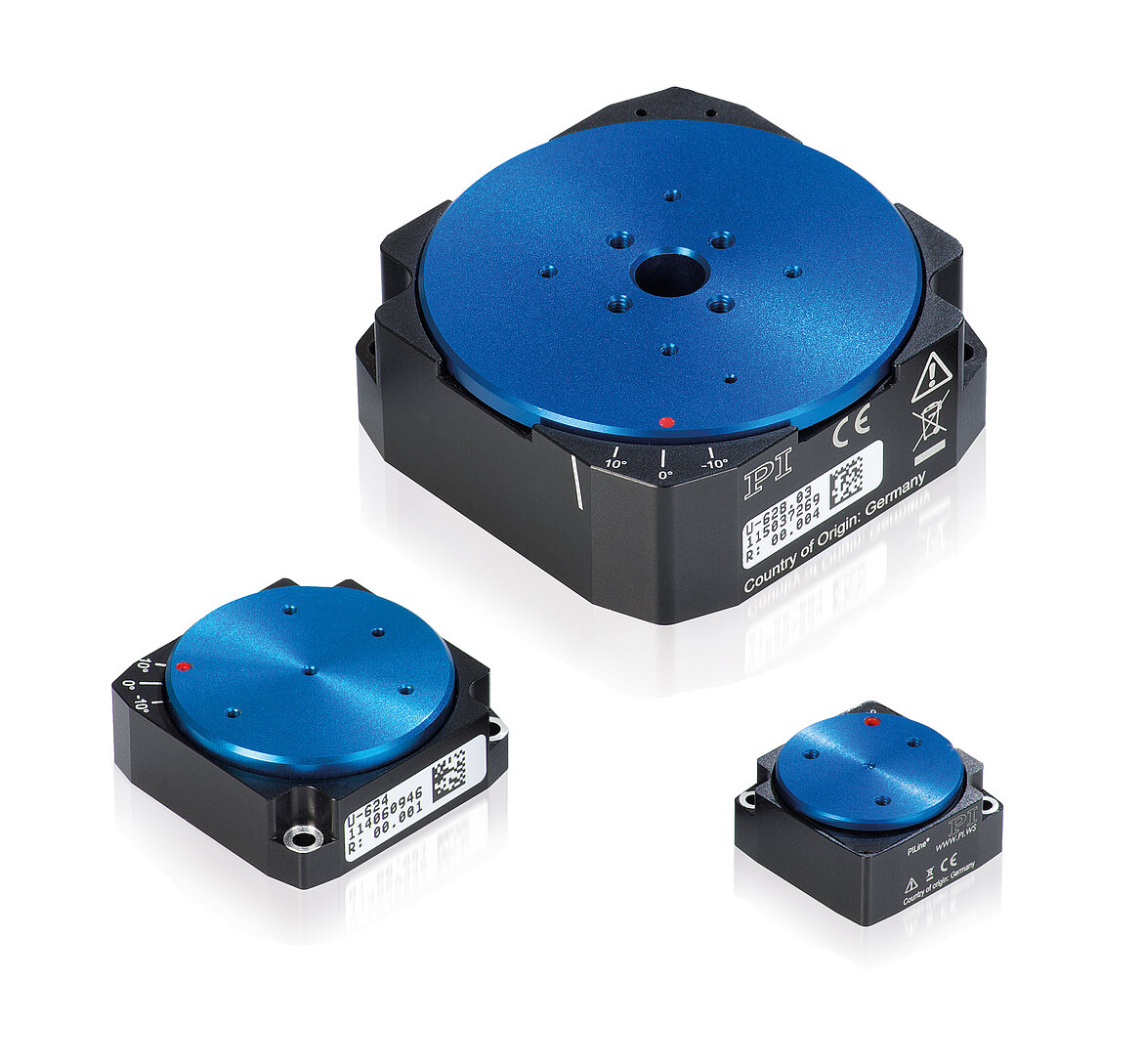
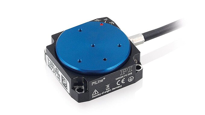
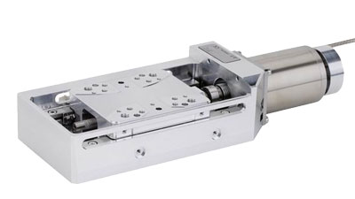
Piezoelectric motors can be operated in open-loop mode, however there are no defined “indents” as with stepper motors. For precision positioning applications with high repeatability, a position sensor (linear or rotary encoder) is added to provide feedback to a closed-loop motion controller. Typical PIline® motor driven linear stages, such as the U-780 XY microscope stage, are available with travel ranges up to 135mm. Depending on the size and encoders, velocities of 200mm/sec and resolutions of 10nm are feasible. For rotary tables such as the U-651 that use two rectangular piezo transducers at 180 degree spacing, up to 540deg/sec closed-loop angular velocity with 4µrad encoder resolution can be achieved. When "at rest", or powered down, the piezoceramic motors are self-clamping with excellent in-position stability. Another advantage of piezoelectric direct drive motors is their minute size, allowing for the design of high precision, yet very small linear and rotary stages. In the following, we are looking at the behavior of the U-624 miniature rotary stage, which is the second smallest standard rotary stage available from PI based on an ultrasonic motor.
3 Materials in Magnetic Fields
When a material is introduced into a magnetic field, it starts to interact physically. These interactions can influence the desired magnetic field to an unacceptable extent or can also disturb the function of electro-mechanical systems in the magnetic field. If these interactions are adverse, traditional electromagnetic motors cannot be used and instead so-called "nonmagnetic" drives are employed.
In nature, there are various forms of magnetism that cause different degrees of physical interaction.

The magnetic flux density B (or, in everyday language, magnetic field) is linked with the magnetic stimulus H via the permeability. The permeability is made up of the natural constants of the permeability µ0 and the material-based relative permeability µr. In everyday life, the magnitude of the magnetic flux density ranges from the strength of the earth's magnetic field with 20-70µT [4] to magnetic resonance scanners with 7T [5].
Diamagnetic materials form a field that opposes the external stimulus. This is because the moving electrons in the material are deflected by the external field, causing the buildup of a field that opposes the external field. The following applies for the relative permeability< 1. The diamagnetic effect is very minor, disappears when the external field is switched off, and occurs for all materials. It often gets superimposed by the paramagnetic or ferromagnetic effect. An example of the diamagnetic effect is the levitation of pyrolytic graphite above permanent magnets.
In the case of paramagnetic materials, microscopic dipoles in the material line up in the external magnetic field, leading to an increase of the field in the material. Hence, paramagnetic materials are drawn into a field. In this case, µr > 1 applies to the relative permeability. On removing the external field, the effect also disappears.
Ferromagnetic materials behave in a similar way to paramagnetic materials; the difference being that when the external field is removed, a so-called "remnant polarization" remains, and the actual material creates a magnetic field. In this case, the relative permeability µr >> 1 can reach values of up to 10^6. Whereas forces can only be proven using complex tests for diamagnetic and paramagnetic materials, these are far stronger for ferromagnetic materials. Permanent magnets made of neodymium iron boron are an impressive example of highly magnetic interaction forces.
Therefore, in positioning systems that are not meant to influence the magnetic field only diamagnetic and paramagnetic materials should be used. In other words, materials with a relative permeability of approximately 1. In this case, the influence of the internal magnetic fields from the respective components on the external magnetic fields is very low, meaning that the influence on the application or on the positioning system is insignificant. Hence, if possible, for non-magnetic applications the use of (strong) ferromagnetic materials should be avoided.
3.2 Selecting Materials – Typically Used Materials for (Non) Magnetic Applications
The knowledge of usable materials and their relative permeability is essential for setting up a non-magnetic system that does not influence the magnetic field of a sensitive environment. Whereas plastics and ceramics are usually diamagnetic, metals may have paramagnetic or ferromagnetic properties. The following table lists some of the materials which, e.g., can be used in non-magnetic stages with the PILine® drive.
Material | µr | for | Source |
Air | 1.00000036 | N/A | |
Metals |
|
|
|
Aluminum | 1.000021 | 7 T | Calculated from [6] |
Copper | 0.9999904 | 7 T | Calculated from [6] |
CuBe2 | 1.00002
| N/A | |
CuSn6 | 0.99999912 - 1.000062 (0 – 0.09 % Fe) | N/A | Calculated from [8] |
Gold | 0.999966 | 7 T | Calculated from [6] |
Silver | 0.999976 | N/A | Calculated from [9] |
96/4 SnAg | 1.00000060 | 7 T | Calculated from [6] |
Titanium (Grade 1) | 1.000178 | N/A | |
TiAl6V4 (Grade 5) | 1.00005 | N/A | |
Tungsten | 1.000070 | N/A | Calculated from [9] |
Ceramics |
|
|
|
Al2O3 | 0.999986 | 7 T | Calculated from [6] |
PZT | 0.9999942 | 9.4 T | Calculated from [11] |
Si3N4 | 0.999986 | 7 T | Calculated from [6] |
SiC | 0.999988 | N/A | Calculated from [9] |
ZrO2 | 0.9999915 | N/A | Calculated from [9] |
Plastics |
|
|
|
FR4 PCB | 0.9999963 | 9.4 T | Calculated from [11] |
Kapton | 0.9999911 | 9.4 T | Calculated from [11] |
PA6 natural | 0.9999905 | 9.4 T | Calculated from [11] |
PEEK | 0.9999907 | 9.4 T | Calculated from [11] |
PPS | 0.9999908 | 7 T | Calculated from [6] |
PTFE (Teflon) | 0.999990 | 9.4 T | Calculated from [11] |
PVC, grey | 0.999989 | 9.4 T | Calculated from [11] |
Tab. 1 Material values for relative permeability µr
Cold forming causes austenitic corrosion-resistant steels to form friction or deformation martensite, meaning that materials with a low relative permeability in their original state subsequently have a much higher µr. A material that very clearly shows this behavior is 1.4305. Hence, the relative permeability may be between 1.05 and 3.42, depending on the extent of deformation. This particularly needs to be considered when using austenitic corrosion-resistant standard parts as, in most cases, there is no information available on the degree of cold deformation.
Degree of Deformation | µr | for | Source |
0 % | 1.003 | N/A | |
10 % | 1.050 | N/A | |
20 % | 1.620 | N/A | |
30 % | 3.420 | N/A |
Tab. 2 Material values for the relative permeability µr for different degrees of deformation of 1.4305

4 Tests and Measurement of Precision Rotation Stages in Magnetic Fields
Source: [13]
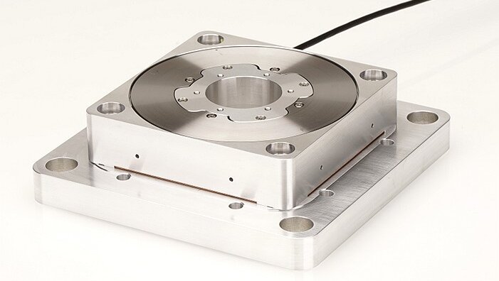
The Research Center Jülich (Forschungszentrum Jülich) has been using rotation stages with PILine® piezo motors for applications in high magnetic fields. For the exact characterization of dipole magnets, it was necessary to determine the influence of the positioner on the subsequent characterization of the magnets. To do this, they measured both a U-624.03 PILine® standard COTS (commercial off the shelf) rotary positioner and a special modified version, optimized for nonmagnetic environments. The small size of the U-624.03 miniature rotation stage with a footprint of 30 x 30 mm² and a height of 12mm make it ideal for applications with limited space.
The following illustrates the measurement setup and the results from the investigations at the Forschungszentrum Jülich.
4.1 Measurement Setup
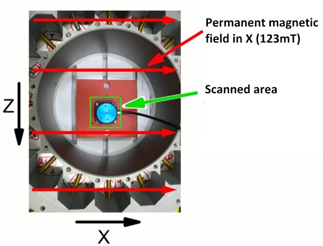
The magnetic measurements of the positioners took place in a measuring chamber at the Forschungszentrum Jülich and is illustrated in Fig. 3 above. An external permanent magnetic field of 123mT was created that was aligned along the positive x axis. The field component thus induced in the Y direction was scanned in the area illustrated in green at approximately 1mm above the rotor surface of the PILine® rotary stages, with the cable always placed to the right-hand side.
4.2 Measurement Results
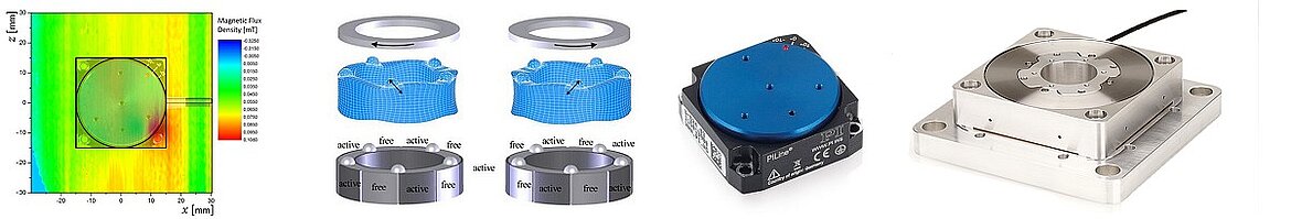
In a first step, the U-624.03 standard rotation stage was measured in the external magnetic field of 123 mT containing ferromagnetic components. Hence, it was possible to measure the values of the field component in Y at approximately 1mm above the rotor level; the values ranged between -800 and 800 µT. The following figure shows the results of this measurement. Here, the external contour is shown as a square, the positioner's rotor as a circle, and the cable as a line pointing to the right.
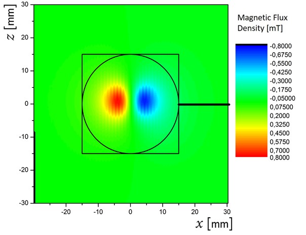
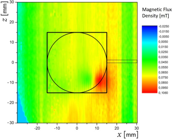
With the standard stage, two poles are formed, visible here as a red and a blue area (Fig 4), in which the field lines are vertical to the image plane and run into or out of it. The standard rotation stage has a ball bearing made of chromium steel near the rotor surface that causes the high measurement values.
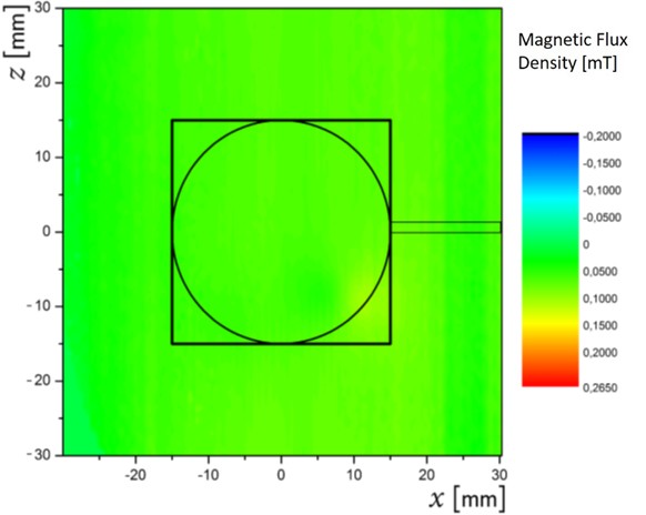
For the modified U-624 rotator, all ferromagnetic components were replaced by suitable components with low relative permeabilities. Relevant modifications were all-ceramic ball bearings, titanium screws, as well as numerous changes of components on the internal PCB. The previously described measurements in the magnetic field were also repeated with this modified rotary positioner. During a first measurement, even when run with a higher resolution measuring range of -200 to 265 µT (Fig. 5), no obvious influences on the components used in the positioner are visible. The magnetic field appears almost homogenous. Therefore, a second measurement with even higher resolution and a measuring range of -25 to +106 µT was done to record and illustrate the significantly lower field values (Fig. 6).
The maximum stray field of 106µT originating from the modified U-624 positioner can be seen in the bottom right hand corner of Fig. 6, resulting from the integrated encoder head required for closed-loop position-controlled operation of the stage.
Thanks to the described modifications, it was possible to reduce the measured magnetic field value by ~87% compared with the standard COTS unit, and at 106µT, this is a very low value. Hence, the modified positioner is suitable for many non-magnetic applications.
5 Function Tests in External Magnetic Fields
Source: [13]
In addition to the magnetic flux density measurements, function tests with the rotary stage exposed to high magnetic fields were also among the investigations conducted at the Forschungszentrum Jülich. For their target dipole magnet characterization application, the positioners must be able to move a measuring probe in the high magnetic field in order to exactly characterize the dipole magnets. For these tests, both the COTS and custom U-624 PILine® rotation stage (described in Section 4) were tested. A PI C-867.1U closed-loop motion controller was used to operate the stages, controlled by PIMikroMove® software.
5.1 Measurement Setup
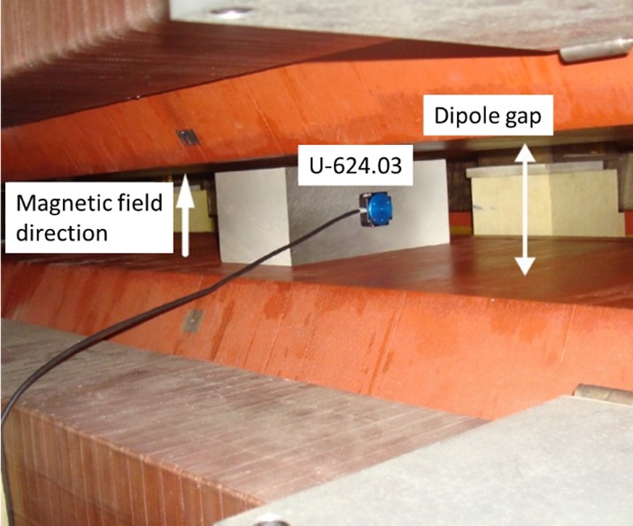
The miniature rotary positioners were mounted on a plastic block and installed into the gap of a dipole magnet with a maximum static field of 1.8T. The direction of the magnetic field was vertical (see the Fig. 7), or aligned parallel to the axis of rotation, and the positioners were in the middle of the dipole field.
5.2 Measurement Results
Both stages worked well in reference mode and position control mode, without errors up to the maximum magnetic field of 1.8T. In the process, the function of the stages was always within spec; both with the perpendicular or parallel alignment of the field to the axis of rotation. Rotation speeds of up to 720°/sec at 1.8T were also tested successfully.
6 Summary
An electro-mechanical system that is brought into a magnetic field interacts with it. It can influence the magnetic field significantly, or, on the other hand, the magnetic field can destroy the electro-mechanical system or disturb its function. Therefore, when selecting a closed-loop precision positioner for operation in magnetic fields, the demands on the choice of materials and their non-magnetic properties are very high.
The relative magnetic permeability µr can be used as a measure of the material-specific property to interact with the magnetic field. Systems to be used in the environments described above should consist of materials that are close to a µr value of 1.
The magnetic flux measurements used in this investigation proved the excellent non-magnetic properties of a modified rotation stage based on the U-624 from PI. The investigated positioning system could also be operated smoothly and reliably in high magnetic fields of up to 1.8T.
PILine® ultrasonic piezoceramic motors use the inverse piezoelectric effect, where deformation of a ceramic transducer takes place on a crystalline level and is, consequently, not affected by magnetism.
In addition to linear motion stages and rotary system, PI can also provide non-magnetic multi-axis stages and other custom motion systems.
7 Acknowledgements
PI would like to thank all members of the HEDI group from the Forschungszentrum Jülich. We would like to thank Dr. Helmut Soltner, Dr. Ulf Bechstedt, and Dr. Ilhan Engin for their in-depth investigations into the magnetic field, for providing the test results for this white paper, and for their consistently open and friendly approach.
8 Author
Thomas Polzer is a development engineer for piezo drives & systems at Physik Instrumente (PI) GmbH & Co. KG.
9 Piezo Motor Stages from PI
Talk to a PI Engineer about your precision motion control applications. For additional information, take a look at this overview of piezo motor stages.
10 List of References
[1] W. H. Hayt Jr. und J. A. Buck, Engineering Electromagnetics, 8th edition, New York: McGraw-Hill, 2012.
[2] N. Ida, Engineering Electromagnetics, New York: Springer science & business media, 2000.
[3] W. D. Callister Jr., Materials science and engineering : An introduction - 7th ed., New York: John Wiley Sons, Inc., 2007.
[4] Deutsches GeoForschungszentrum, „Magnetfeld der Erde - Unser dynamischer Schutzschild,“ [Online]. Available: https://media.gfz-potsdam.de/gfz/wv/doc/infothek/leaflets/Faltblatt_Magnetfeld_dt.pdf. [Zugriff am 20 07 2020].
[5] Siemens Healthineers, „Magnetresonanztomographie,“ Siemens Healthineers, [Online]. Available: https://www.siemens-healthineers.com/de/magnetic-resonance-imaging. [Zugriff am 16 11 2020].
[6] F. D. Doty, G. Entzminger und Y. A. Yang, „Magnetism in high-resolution NMR probe design. I : general methods,“ Concepts in Magnetic Resonance, Volume 10, Issue 3, pp. 133-156, 07 12 1998.
[7] NIPPON THOMPSON CO., LTD., „IKO: non-magnetic linear motion rolling guide series : CAT-5937,“ 2012. [Online]. Available: https://www.ikont.co.jp/global_data/download/pdf_catalog/cat5937.pdf. [Zugriff am 20 04 2020].
[8] Deutsches Kupferinstitut, „Werkstoffdatenblatt CuSn6,“ 2005. [Online]. Available: https://www.kupferinstitut.de/wp-content/uploads/2019/11/CuSn6-1.pdf. [Zugriff am 30 03 2020].
[9] D. R. Lide und ed., "Magnetic susceptibility of the elements and inorganic compounds" in CRC handbook of chemistry and physics, Boca Raton: Taylor & Francis, 2006.
[10] ThyssenKrupp, „Titan - Werkstoff mit Perspektive,“ 2012. [Online]. Available: https://www.thyssenkrupp-schulte.de/. [Zugriff am 09 05 2016].
[11] M. C. Wapler, J. Leupold, I. Dragonu, D. von Elverfeld, M. Zaitsev und U. Wallrabe, „Magnetic properties of materials for MR engineering, micro-MR and beyond,“ Journal of Magnetic Resonance, volume 242, pp. 233-242, 08 04 2014.
[12] Informationsstelle Edelstahl Rostfrei, „Merkblatt 827 : Magnetische Eigenschaften nichtrostender Stähle,“ 2013. [Online]. Available: https://www.edelstahl-rostfrei.de/fileadmin/user_upload/ISER/downloads/MB_827.pdf. [Zugriff am 04 05 2016].
[13] I. Engin, „Bericht Forschungszentrum Jülich über die Charakterisierung der Rotationstische,“ intern, 2016.


Blog Categories
- Aero-Space
- Air Bearing Stages, Components, Systems
- Astronomy
- Automation, Nano-Automation
- Beamline Instrumentation
- Bio-Medical
- Hexapods
- Imaging & Microscopy
- Laser Machining, Processing
- Linear Actuators
- Linear Motor, Positioning System
- Metrology
- Microscopy
- Motorized Precision Positioners
- Multi-Axis Motion
- Nanopositioning
- Photonics
- Piezo Actuators, Motors
- Piezo Mechanics
- Piezo Transducers / Sensors
- Precision Machining
- Semicon
- Software Tools
- UHV Positioning Stage
- Voice Coil Linear Actuator
- X-Ray Spectroscopy