Nanopositioning Stages NANOPOSITIONING BLOG
Definition
Nanopositioning device: Drive system & guiding system are frictionless and not limited in resolution.
Micropositioning device: Other drive and guiding systems, such as screw drives, inertial drives, friction drives, ball bearings, roller bearings, etc.
Piezo Nanopositioning Stages, Air Bearing Stages, Magnetic Bearings, and Traditional Micropositioning Stages
There are several ways to achieve nanometer precision motion. The best positioning systems avoid friction all together, in both the drive system (motor) and in the guiding system (bearings). Frictionless bearings also avoid the bearing rumble caused by balls and rollers and provide vibration-free motion with highly constant velocity.

For short travel ranges, piezo drives with frictionless flexure guidance are the technology of choice. They combine fast response, extreme guiding precision, very long, maintenance-free service life and can easily achieve sub-nanometer step sizes. Due to the high stiffness and low inertia, piezo flexure stages can also achieve extremely fast step and settle times in the millisecond or microsecond range and high scanning rates with hundreds or thousands of Hz, both important features in optics, alignment and semiconductor test and manufacture.
For longer travel, positioning stages with frictionless air bearings and linear motors are available. More on air bearing stages

Another option to go frictionless is known as magnetic levitation (magnetic bearings).
Positioning stages with conventional guiding systems (crossed roller bearings, ball bearings, etc.) and drive systems (leadscrews or ball screws) cannot provide the same performance in terms of geometric precision, responsiveness and resolution, but they also have many applications. See more examples of motorized stages.
For detailed information on piezo flexure-based nanopositioning and scanning systems, read on:
Low Inertia = Higher Speed
With piezo drives, capable of accelerations of up to 10,000 g, and their low moved mass, such piezo stages can provide significantly higher scanning speeds than motorized systems.
Why Flexures?
Flexure motion is based on the elastic deformation (flexing) of a solid material. Friction and stiction are entirely eliminated, and flexures exhibit high stiffness, load capacity and resistance to shock and vibration. Flexures are maintenance free and not subject to wear. They are vacuum compatible, operate over a wide temperature range and require neither lubricants nor compressed air for operation.
Travel Ranges
The latest flexure guided nanopositioning stages provide travel ranges close to 2 mm (see P-629 PIHera® stages). For longer travel ranges, the novel NEXLINE® and NEXACT® nanopositioning motors are available. These motors were developed to overcome the limitations of nanopositioning devices in the semiconductor industry.
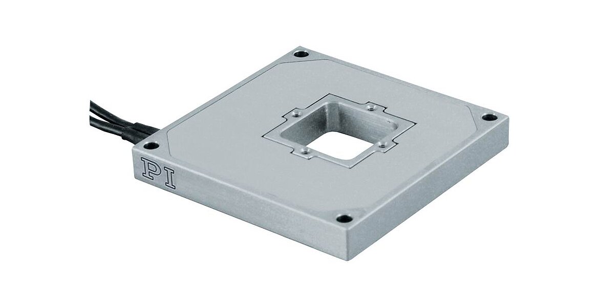
Zero-Runout Multilink Flexures: Excellent Guiding Accuracy
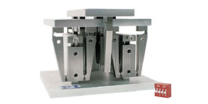
The multilink flexure guiding systems employed in most PI piezo nanopositioners (Fig. ) eliminate cosine errors and provide bidirectional flatness and straightness in the nanometer or microradian range. This high precision means that even the most demanding positioning tasks can be run bidirectionally for higher throughput.
Lifetime / Ceramic Encapsulation
PI nanopositioning systems employ the patented, award-winning PICMA®piezo actuators, the only actuators with cofired ceramic encapsulation. The PICMA® piezo technology was specifically developed by PI’s piezoceramic division to provide higher performance and lifetime in nanopositioning applications.
Multilayer piezo actuators are similar to ceramic capacitors and are not affected by wear and tear. PI nanopositioning systems are designed to be driven at lower voltages than most other piezo systems (100 V vs. 150 V). The research literature, PI’s own test data and 30+ years of experience all confirm that lower average electric fields, lead to longer lifetime.
In addition PI’s monolithic ceramic-encapsulated design provides better humidity protection than conventional polymer-film insulation. Diffusion of water molecules into the insulation layer is greatly reduced by the use of co-fired, outer ceramic encapsulation (fig. ). Humidity is the main influence on the longterm reliability in low-dynamics or quasi-static operation modes, where the piezo actuator is supplied with a DC voltage to maintain a position for a long time.
100 Billion Cycles - Lifetime Tests Prove new Actuator Design
Comparative tests with both PICMA® and conventional piezo actuators have proven the positive effects of the ceramic encapsulation. While polymer-coated piezos typically only survive 30 days of continuous operation - PICMA® actuators are still working after many years. Other tests by NASA have shown 100 Billion cycles can be reached with no failures.

To suit an application requiring 10 years minimum lifetime under cryogenic conditions, accelerated lifetime tests with PICMA® piezo actuators have been successfully performed. Inserted in a cryogenic bath of liquid nitrogen (75 K), the piezo is placed in a vacuum chamber (2 • 10-3 mbar) and subjected to dynamic operation at 90% of the maximum voltage range (>105 V) with an operating frequency up to 1000 Hz. After one month of continuous operation there were no degradations in piezo performance to be measured, neither mechanic concerning the displacement, nor electrical concerning electrical capacitance or resonant frequency. (Dr. Bosotti et al., University of Milano, Italy, 2005 )
Measuring Nanometers: Stage Metrology Selection
Achieving nanometer and subnanometer precision requires more than a piezo stage capable of making moves on this precision scale. The stage internal metrology system must also be capable of measuring motion on the nanometer scale. The five primary characteristics to consider when selecting a stage metrology system are linearity, sensitivity (resolution), stability, bandwidth, and cost. Other factors include the ability to measure the moving platform directly and contact vs. noncontact measurement.
For long travel motorized stages, optical encoders are the preferred choice, where the latest models can achieve sub-nanometer resolution. For the utmost precision, external interferometers are another option.
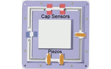
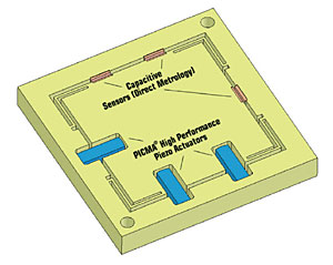
PI capacitive sensors: measure the gap between two plates based on electrical capacitance. These sensors can be designed to become an integral part of a nanopositioning system, with virtually no effect on size and mass (inertia). Capacitive sensors offer the highest resolution, stability, and bandwidth. They enable direct measurement of the moving platform and are noncontact. Capacitive sensors also offer the highest linearity (accuracy). PI's capacitive sensors / control electronics use a high-frequency AC excitation signal for enhanced bandwidth and drift-free measurement stability (subnanometer stability over several hours, see here). PI’s exclusive ILS linearization system further improves system linearity. If used with PI’s digital controllers, digital polynomial linearization of mechanics and electronics makes possible overall system linearity of better than 0.01%. Capacitive sensors are the metrology system of choice for the most demanding applications.
Johnson Noise Free: Capacitive sensors are not plagued by the intrinsic noise found in all resistance type sensors (Johnson noise) such as piezo-resistive or other resistive sensors. They offer advantages due to their well-understood characteristics, and high linearity


Strain gauge sensors: There are two commonly used types of strain gauge sensors: piezo-resistive (semicoductor strain gauges) and film type sensors. They derive position information from a change in their resistance when stretched or compressed. They need to be bonded to a piezo stack or—for enhanced precision—to the guiding system of a flexure stage. Piezo resistive sensors are extremely small and are often used in AFMs. Either type strain gauge sensor offers high resolution and bandwidth and is typically chosen for cost-sensitive applications. As a contact type sensor, it infers position from strain - for nanopositioning the position of the moving platform is inferred from a measurement at the lever, flexure or stack. PI employs full-bridge implementations with multiple strain gauges per axis for enhanced thermal stability. PI's PICMA® drive technology also enables higher performance of actuator-applied strain gauge sensors.
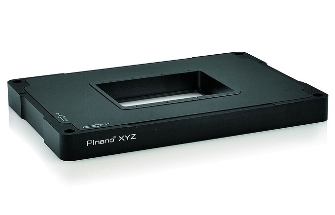
PRS : Piezoresistive sensors provide very high resolution but cannot match the linearity and stability of capacitive sensors. PRS are for example employed in PI's P-545 PInano stage series for optical microscopy applications. For many optical microscopy applications the stability and linearity of piezoresistive sensors is sufficient.
Johnson Noise: Resolution of all resistance type sensors such as strain gauge sensors and piezo-resistive sensors is limited by the intrinsic Johnson noise.
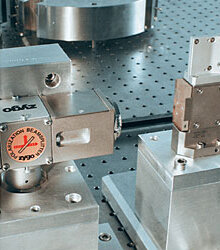
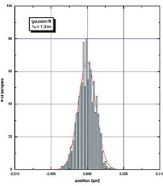
Table 1
| Sensor Type | Sensitivity* (Resolution) | Linearity* | Stability* / Repeatability | Bandwidth* | Metrology Type | Excitation Signal |
| Capacitive | Best | Best | Best | Best | Direct / Noncontact | AC |
| Strain (Film) | Good | Better | Good | Good | Inferred ** (Indirect) / Contact | DC |
| PRS | Very Good | Good | Good | Good | Inferred ** (Indirect) / Contact | DC |
* Note. The ratings describe the influence of the sensor on the performance of the whole nanopositioning system. Resolution, linearity, repeatability, etc. specifications in the PI product data sheets indicate the performance of the complete system and include the controller, mechanics and sensor. They are verified using external nanometrology equipment (Zygo Interferometers). It is important not to confuse these figures with the theoretical performance of the sensor alone.
** Strain type sensors (metal foil, semiconductor, or piezoresistive) infer position information from strain.
Dynamics, System Behavior, Frequency Response / Step Response
One of the advantages of piezo systems is their ability to react rapidly to an input signal. As a rule of thumb, the higher the resonant frequency of the system, the faster the response. For open-loop systems the shortest rise time is approximated by
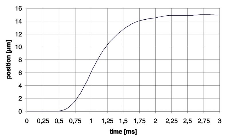
Tmin = time [s]
f0 = resonant frequency [Hz]
This theoretical value (basically switched operation) requires an amplifier with sufficient output current and slew rate and would induce significant amounts of overshoot and ringing. It is not the fastest way to get to a stable position.
Read Methods to Improve Piezo Dynamics for more information.
For closed-loop systems, the performance of the servo controller also plays a significant role. Digital controllers with advanced filtering techniques can provide much faster response (while eliminating keeping overshoot and oscillation) than simple analog controllers.
The phase response of a piezo actuator system can be approximated by a second order system and is described by the following equation:
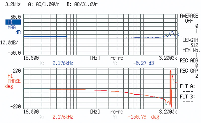
j = phase angle [deg]
Fmax = resonant frequency [Hz]
f = operating frequency [Hz]
More information on piezo actuators and motors can be found in the piezo motion tutorial and in the Dynamic Operation section on the PI Ceramic Website
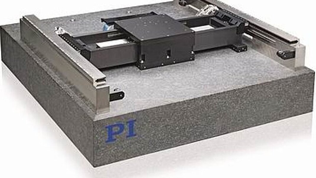
Parallel and Serial Kinematic Stage Designs
There are two ways to achieve multi-axis motion: parallel and serial kinematics. Serial kinematics (nested or stacked systems) are simpler and less costly to implement, but they have some limitations compared to parallel kinematics systems (see here for more information).
Serial Kinematics for Lower Cost / Standard Applications
In a multi-axis serial kinematics system, each actuator (and usually each sensor) is assigned to exactly one degree of freedom. Serial kinematic designs have advantages when it comes to cost and simplicity, and work very well for most standard applications.
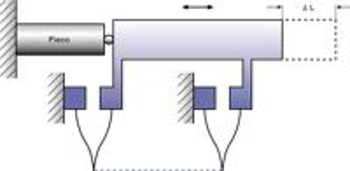
No Crosstalk?
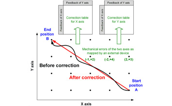
However, the manufacturing precision of even the best machines (and technicians) does not allow for crosstalk-free mechanics, at least not at the nanometer level, even in quasistatic operation. For many applications this is not a problem at all. In a parallel kinematics multi-axis system, all actuators act directly on the same moving platform (relative to ground), enabling reduced size and inertia, and the elimination of microfriction caused by moving cables (Fig. ). This way, the same resonant frequency and symmetrical dynamic behavior can be obtained for both the X and Y axes. The advantages are higher dynamics and scanning rates, better trajectory guidance as well as better reproducibility and stability. Still, without the proper test metrology / instrumentation these advantages can easily be overlooked, and a serial kinematics system may appear to be perfect. For an inexperienced designer it could then be very tempting to draw the conclusion there is no cross talk (see also "Coupled and Uncoupled Motion..." below).
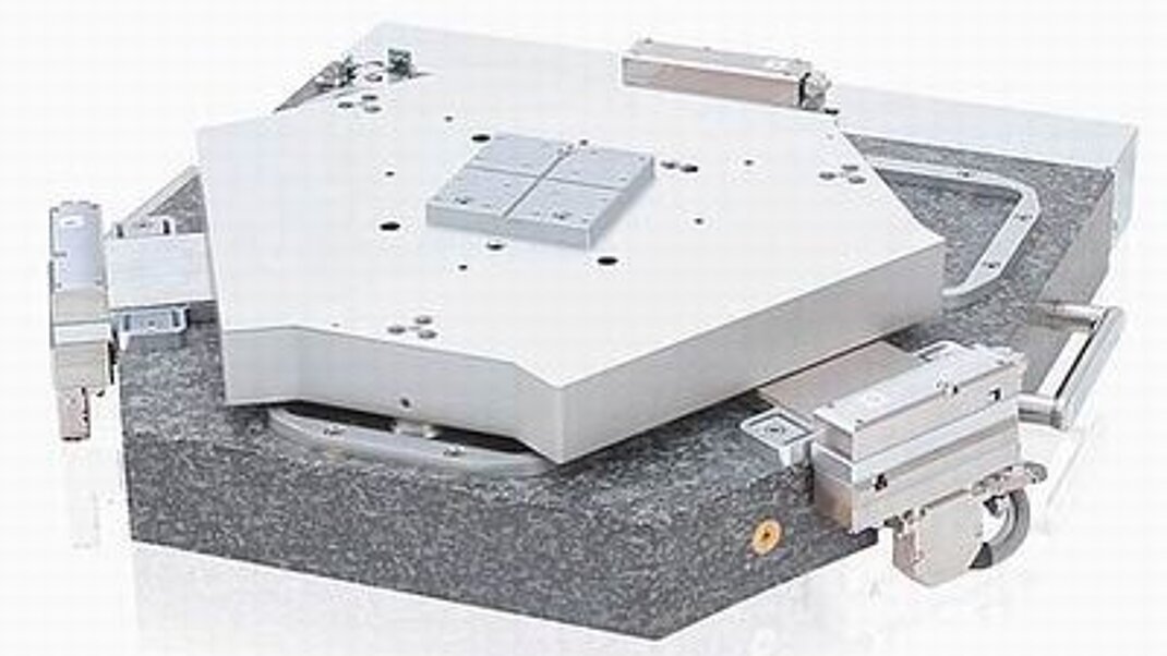
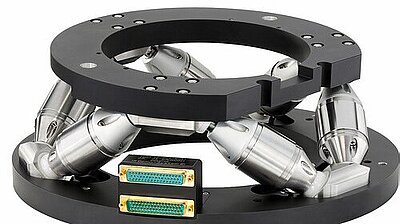
Parallel Kinematics for Highest Multi-Axis Precision / Dynamics.
For the ultimate in dynamics straightness/flatness/orthogonality and for coordinate transformation situations (such as rotating about an arbitrary point in space), parallel kinematics is required. Parallel Kinematics systems, if designed well, are superior to serial kinematics systems. A comparison that comes to mind is the electronic computer and the slide ruler. Both can be used to solve many problems, but a computer can do more, faster. To reap the benefits of parallel kinematics, you must have high-bandwidth, direct drivetrain-output metrology, so the workpiece can be simultaneously observed and controlled in multiple degrees of freedom.
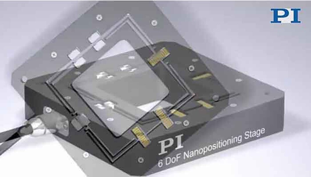
Because it takes more knowledge, experience and more advanced controllers to produce a good parallel kinematics precision positioning system, inexperienced designers may avoid that challenge dismissing the technology as unpredictable, uncontrollable. Everyone who has seen a modern hexapod 6-axis motion system compared to a classical stack of translation and rotation stages will immediately understand the benefits of parallel kinematics.
Coupled and Uncoupled Motion, Static and Dynamic
Serial kinematics are sometimes referred to as uncoupled motion systems vs. coupled motion systems for parallel kinematics. When it comes the nanometer realm, there is no uncoupled motion. By nesting or stacking a second and/or third axis onto a translation stage, there will be an influence on the first axis. Any load attached will have a further influence on all axes, even when at rest. Since we are talking about positioning, things are not always at rest, actually most nanopositioning / scanning applications require very high dynamics. The seemingly uncoupled multiaxis-system then provides coupled (unwanted) motion in many degrees of freedom, that cannot be detected by its internal serial metrology sensors and hence goes partially uncontrolled. These errors may not be critical in many applications, but can be detrimental in some others.
Direct Parallel Metrology: All Motion Inside the Servo Loop
Multi-Axis Measurements Relative to a Fixed Reference
Parallel kinematics facilitates implementation of Direct Parallel Metrology—measurement of all controlled degrees of freedom relative to ground. This is a more difficult design to build but it leads to clear performance advantages.
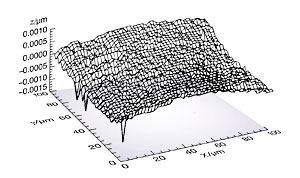
The parallel-kinematics / parallel metrology system “sees" motion in all controlled degrees of freedom and will respond to it. This means that all motion is inside the servo-loop, no matter which actuator (or unwanted external force / crosstalk) may have caused it, resulting in superior multi-axis precision, repeatability and flatness, as shown in Fig. . Direct parallel metrology also allows stiffer servo settings for faster response. Off-axis disturbances—external or internal, such as induced vibration caused by a fast step of one axis—can be damped by the servo.
Controller Choice / Interfacing
Analog and Digital Controllers
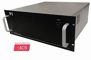
PI manufactures a large variety of analog and digital piezo nanopositioning controllers. For traditional motion control, our EtherCat-based ACS motion controllers offer advanced control functions, such as, PILOT, ServoBoost, NanoPWM, Input Shaping, and AI based self-learning algorithms.
For piezo-based stages, state-of-the-art PI digital control systems offer several advantages over analog control systems: coordinate transformation, real-time linearity compensation and elimination of some types of drift. Digital controllers also allow virtually instant changes of servo parameters for different load conditions, etc. However, not all digital controllers are created equal. Poor implementations can add noise and lack certain capabilities of a well-designed analog implementation, such as fast settling time, compatibility with advanced feed-forward techniques, stability, and robust operation. Learn more on digital vs. analog piezo controllers for closed-loop operation»
PI digital controllers can download device-specific parameters and calibration information from ID-chip-equipped nanopositioning stages, facilitating interchangeability of nanomechanisms and controllers.
All PI nanopositioning controllers (analog and digital) are equipped with one or more user-tunable notch filters. A controller with notch filter can be tuned to provide higher bandwidth because side-effects of system resonances can be suppressed before they affect system stability. For the most demanding step-and-settle applications, PI’s exclusive Mach™ InputShaping® implementation is available as an option.
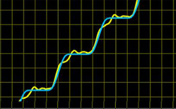
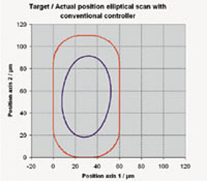
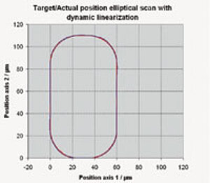
Improved Piezo Control: Digital Dynamic Linearization (DDL) Firmware Upgrade
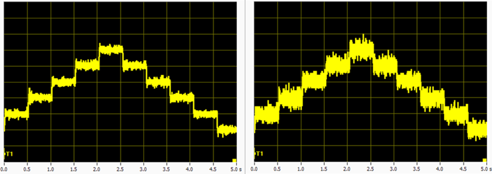
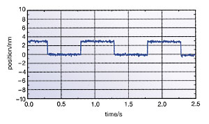
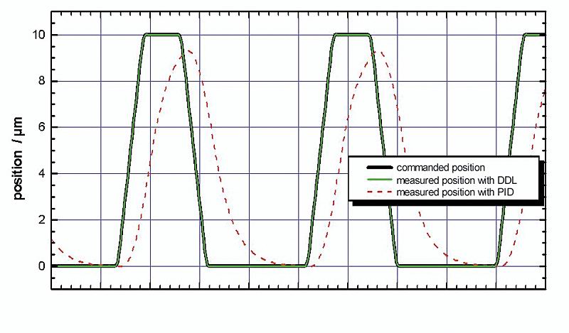
Conventional piezo controllers cannot completely eliminate phaseshift and tracking errors in applications with rapid, periodic motion. This is due in part to the non-linear nature of the piezoelectric material, the finite control bandwidth and the inherent limitations of P-I-D (proportional integral derivative) servo-control, which cannot react before a position error is detected.
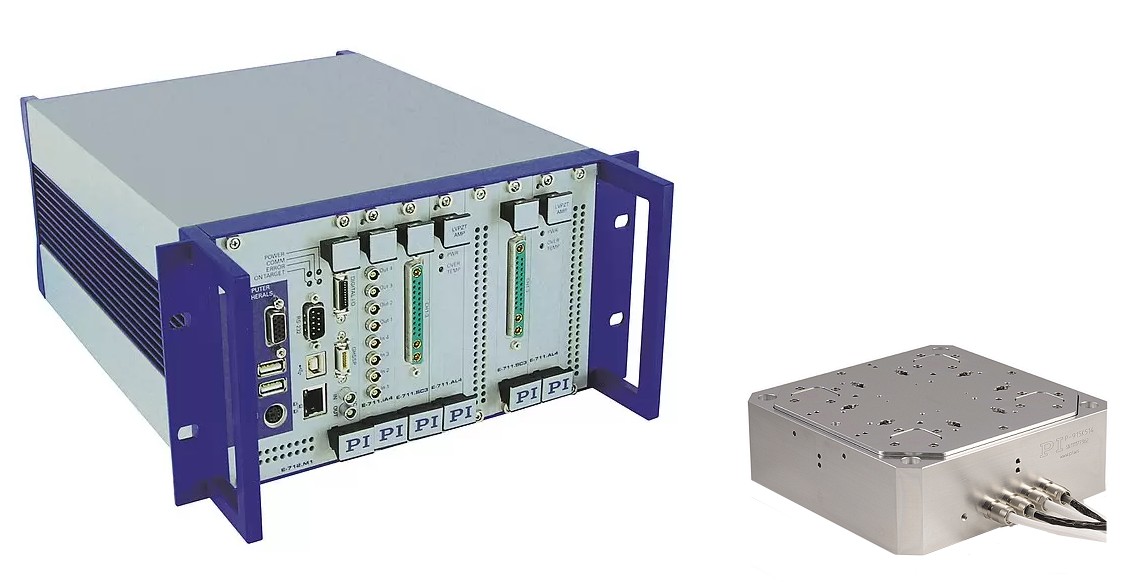
The DDL firmware upgrade option (ordering number E-710.SCN), available with most digital piezo controllers such as the E-754 (single-channel) or the E-712 (multi-channel, modular), solves this problem. This technology, developed by PI, reduces the error between the current and desired position to imperceptible values. The dynamic linearity and effectively usable bandwidth are thus improved by up to three orders of magnitude (1000-fold). DDL is of benefit to single- and multi-axis applications where motion follows a given trajectory repeatedly (see measurement graphs).
Choice of Interface: Digital or Analog or Both?
Analog interfacing provides high bandwidth and remains the most common way of commanding piezoelectric motion systems. It is usually the choice when the control signal in the application is provided in analog form. A key advantage of analog interfacing is its intrinsic deterministic (real-time) behavior, contrasted to the difficulty of accurately timing high-bandwidth communications on present-day multitasking PCs.
However, when analog control signals are not available, or when a significant distance between the control signal source and the nanopositioning controller would affect signal quality, digital interfacing, which must not be confused with digital control, is the preferred choice.
Digital signals can be transferred through copper wires, or for complete EMI immunity, through optical fibers.
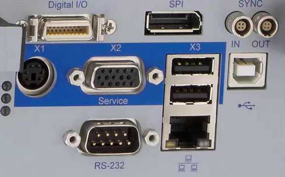
Several types of digital interfaces are typically used in piezo-nanopositioning applications: TCP/IP, parallel-port, USB, RS-232, Fiber Link, IEEE 488 and, with some digital controllers, direct DSP links. For dynamic, high-precision applications, the exact timing of an interface can be significantly more important than the data transfer rate.
Interface Bandwidth vs. Timing / Througput, NanoAutomation®
Piezo-driven stages can respond to a motion command on a millisecond or microsecond time scale.
Many throughput-driven applications require nanometer precision in milliseconds, or NanoAutomation®, capabilities. That is why synchronization of motion commands and data acquisition have a high impact on the quality of many applications, like imaging or micromachining. The USB, for example, was designed to transfer huge blocks of data at high speeds, but exact timing was a much lesser concern. While insignificant in less responsive positioning systems, this kind of non-deterministic behavior may not be tolerable in high-speed tracking or scanning applications. Each motion command—comprising just a few bytes—must be transferred instantaneously and without latency. A lower-bandwidth bus with higher timing accuracy may perform better in many applications.
There are several factors that affect the response of a digital interface: the timing accuracy of the operating system on the controlling computer; the bus timing protocol; the bandwidth of the bus; and, the time it takes the digital interface (in the piezo controller) to process each command. Parallel-port interfaces do not require command parsing and offer the best combination of throughput and timing accuracy.
In addition, to the interface properties, the bandwidth of the nanopositioning system (mechanics and servo) matters. A slow system (e.g. 100 Hz resonant frequency) will not benefit from a responsive interface as much as a high-speed mechanism.
Analog In- and Outputs
Optionally available analog inputs can be configured in a flexible way: either as a control input—the applied voltage can be connected with one of the available axes and is interpreted e.g. as a position value—or as an external sensor—e. g. used as an autofocus signal instead of an integrated sensor. Optional analog outputs allow the control of external power amplifiers or can be used as monitor signal interfaces. The individual data sheets for the controllers inform about number, voltage range (usually ±10 V) and availability of the analog I/Os.
Data Recorder: Data Acquisition and Output
The flexibly configurable data recorder enables simultaneous recording and read-out of input and output signals, such as for sensor positions or control voltages depending on time stamps or using trigger signals.
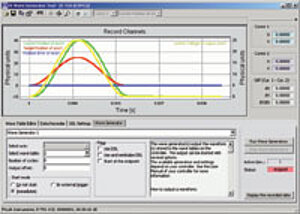
Wave and Profile Generator: Pre-Defined and Programmable Trajectory Profiles
Trajectory profiles of arbitrary, user-defined mathematical functions enable complex 2-axis motion. Depending on the controller used, either time and position data value pairs can be saved (Wave Generator) or complete trajectory profiles with velocity, acceleration and jerk (rate of change of acceleration) can be specified (Profile Generator). The functionality includes:
- Programming of complex functions
- Quick access to common functions (e. g. sine, ramps, triangle and square waves ...)
- Coordination of two axes, e. g. for applications requiring circular motion
- Saving of defined functions in the controller
All controller specific functionalities are available as DLL function calls and LabVIEW VIs, which enables their simple integration in external programs. Additional graphical user interfaces allow convenient selection and customization.
CE Compliance CE & RoHS Compliance
All standard PI nanopositioning systems are fully CE and RoHS compliant.

Extensive Software Support saves Time
Software support is becoming increasingly important in nanopositioning applications. There is a need for flexibility in the vendor's software to enable the user to switch hardware without rewriting the code and to upgrade or switch between various interfaces -USB, TCP/IP, RS-232, real time parallel interfaces, even analog -without starting from scratch. Synchronization between commanded motion and execution of the command can be paramount in leading-edge applications.
Digital controllers come with a large variety of software tools, such as the PIMikroMove graphic user interface or the NanoCapture™ system analysis program. Additional LabVIEW drivers and DLL’s for easy setup, system optimization and integration in application-specific programs are included. Comprehensive documentation, Online Help and sample code offer added value. Even analog systems can be controlled with PI’s LabVIEW driver set, optionally with HyperBit functionality.
PI controllers and software are based on the novel GCS Universal Command Set. This platform independet architecture decouples positioning hardware and controller and allows seamless integration of motion systems into application control software. More on GCS and PI Software Tools.